- 26 -
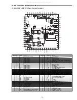
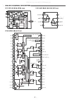
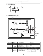
IC BLOCK DIAGRAM & DESCRIPTION
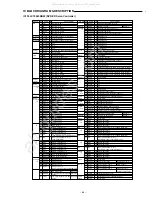
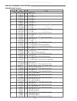
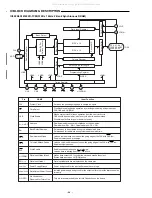
IC800 ZR36742(A/V Decoder)
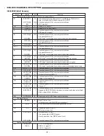
ADC interface (3 pin)
164~166
SDRAM interface (36 pin)
80,82,84,86,
87,89,90,92,
93,95,96,98,
99,101,102,
104
53~55,57~60,
62~64,67,70
72
74
78
76
66,68
71
75
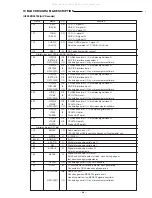
External memory interface (41 pin)
105~113,
117~122
131,133~138,
140,142~150,
152,154
155
129
128
124,126
123
Power supply (52 pin)
15,33,50,56,
65,73,79,88,
94,100,114,
125,139,151,
189,207
1,17,35,61,69,
77,85,91,97,
103,116,127,
141,153,191
48,159
178
180
30,81,132,183
28,83,130,185
158
156
171
168,174,176
163
167
I
I/O
O
O
O
O
O
O
O
O
I/O
O
O#
I/O
O
O
O
O#
I/O
S
S
S
S
S
S
S
S
S
S
S
S
S
SERADC[2:0]
RAMDAT[15:0]
RAMADD[11:0]
RAMRAS#
RAMCAS#
PCLK
RAMDQM
RAMBA[1:0]
RAMCS#
RAMWE#
MEMDA[15:0]
MEMAD[18:0]
MEMAD[19]#
GPCI/O[33]
MEMWR#
MEMRD#
MEMCS[1:0]#
MEMCS[2]#
GPCI/O[31]
GNDP
VDDP
VDDIP
GNDP2
VDDP2
GNDC
VDDC
GNDA
VDDA
VDDDAC
GNDDAC[D,B,P]
GNDADC
GNDADC
Function
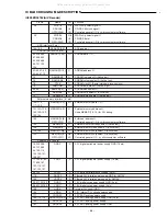
ATAPI chip select signal O.
CD-DSP bit clock signal I.
Controled general I / O by microcomputer software.
ATAPI chip select signal O.
CD-DSP data I.
Controled general I / O by microcomputer software.
ADC analog I.
SDRAM data I / O.
SDRAM address O.
SDRAM low select O (Active low).
SDRAM column select O (Active low).
SDRAM clock O (Same internnal process clock).
SDRAM data mask O (Active high).
SDRAM bank select O.
SDRAM chip select O (Active low).
SDRAM write enable O (Active low).
External memory data I / O.
External memory address O.
Used MEMAD (18 : 16) for PLL debug.
Externaal address O.
Controled general I / O by microcomputer software.
External memory write enable O (Active low).
External memory read enable O (Active low).
External memory chip select O (Active low).
External memory chip select O (Active low).
Controled general I / O by microcomputer software.
3.3V digital peripheral power supply GND (16 pin).
3.3V digital peripheral power supply (16 pin).
3.3V peripheral reference voltage (2 pin).
Filtered 3.3V digital power supply GND for AMCLK.
Filtered 3.3V digital power supply for AMCLK.
1.8V digital core power supply GND (4 pin).
1.8V digital core power supply (4 pin)
Internal PLL oircuit GND.
1.8V internal PLL circuit power supply.
3.3V DAC analog power supply.
3.3V DAC analog power supply GND (3 pin).
3.3V ADC analog power supply.
3.3V ADC analog power supply GND.
Pin No.
38
39
I/O
O#
I#
I/O
O#
I#
I/O
Name
ATCS1#
CDCLK#
GPCI/O[44]
ATCS0#
CDDAT#
GPCI/O[45]
All manuals and user guides at all-guides.com

