−
7
−
3-2. INSTALLATION OF A VZU-COM300
3-2-1. INSTALLING THE BOARD
1. Remove the 6 screws securing the cover (4 on sides, 2 on
rear), and remove the cover.
Remove the 2 screws on the rear cover of the hard disk
recorder, and remove the rear cover.
2. Attach the 2 spacers to the holder, perpendicular to it.
3. Use the 2 screws provided to attach the holder to the inside
bottom of the hard disk recorder, orienting the holder’s printed
“R” to the right.
4. Tilting the interface board slightly, attach the board to the
holder, fitting the spacers into the two holes in the board.
Make sure that the ends of the spacers protrude from the
interface board.
5. Fasten the interface board to the hard disk recorder using
the 2 screws removed in Step 1 (screws for attaching the
rear cover).
6. Align the orientations of harness connectors with the
connectors on the interface board and hard disk recorder,
and plug them in securely, keeping them straight.
When unplugging the connectors, pull them carefully out,
keeping them straight.
7. Attach the cover removed in Step 1, and fasten it with the 6
screws.
3-2-2. SETTINGS AFTER INSTALLATION
After installing the interface board, perform the steps below.
1. Turn the hard disk recorder’s power ON.
2. Set each item in “2. RS-232C/RS-485 SET” in <MAIN MENU
2>.
3. Set “NETWORK CONTROL” in “5. NETWORK SET” in
<MAIN MENU 2> to “ON”.
CAUTION
For instructions regarding connecting to the hard disk recorder
and setting procedures, refer to the manual for the DSR-300.
Harness
Connector
Cover
Screw
Screw
Rear cover
Rear of hard disk recorder
Holder
Spacers should be
perpendicular to
holder
Left
Right
(1)
(2)
Summary of Contents for 175 811 00
Page 2: ... 2 ...
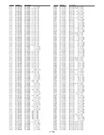
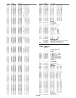
Page 14: ...14 DIODES OSCILLATORS INDUCTORS CAPACITORS ...
Page 15: ...15 ...
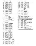
Page 16: ...16 BUZZER RESISTORS ...
Page 17: ...17 ...
Page 18: ...18 ...
Page 19: ...19 ...
Page 21: ......


