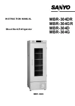
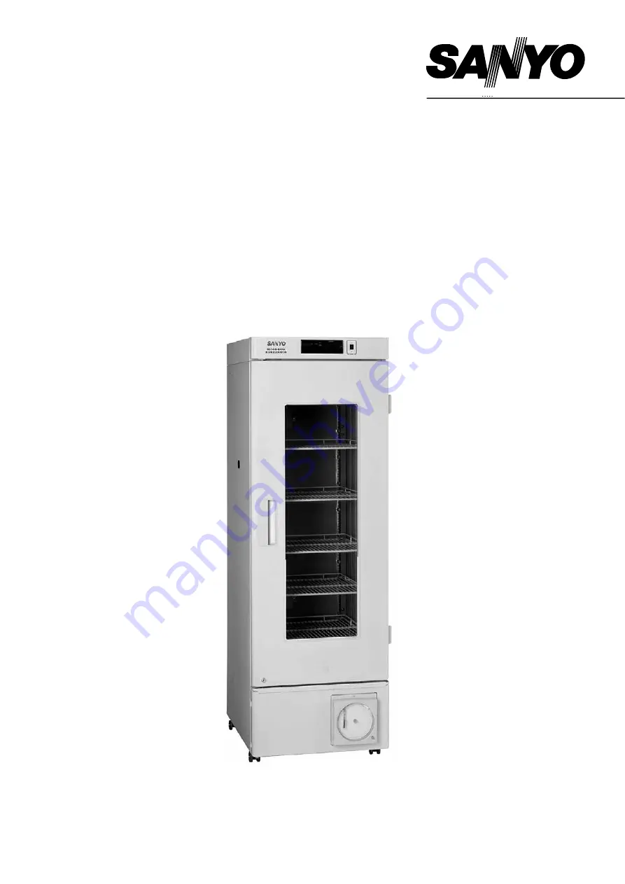
background image


MBR-304DR
MBR-304GR
MBR-304D 
MBR-304G

Blood Bank Refrigerator

INSTRUCTION MANUAL

MBR-304G


Summary of Contents for BLOOD BANK MBR-304DR

Page 1: ...MBR 304DR MBR 304GR MBR 304D MBR 304G Blood Bank Refrigerator INSTRUCTION MANUAL MBR 304G ...

Page 2: ...naccuracies SANYO Electric Biomedical Co Ltd All rights reserved Printed in Japan CONTENTS PRECAUTIONS FOR SAFE OPERATION P 2 CAUTIONS FOR USAGE P 6 ENVIRONMENTAL CONDITIONS P 7 REFRIGERATOR COMPONENTS P 8 INSTALLATION P 11 BEFORE COMMENCING OPERATION P 13 START UP OF UNIT P 15 OPERATING INSTRUCTIONS P 16 ALARMS SAFETY FUNCTIONS P 19 ROUTINE MAINTENANCE P 20 DISPOSAL OF UNIT P 21 TROUBLESHOOTING P...

Page 3: ...t in a hazard to personnel possibly resulting in serious injury or death CAUTION Failure to observe CAUTION signs could result in injury to personnel and damage to the unit and associated property Symbol shows this symbol means caution this symbol means an action is prohibited this symbol means an instruction must be followed Be sure to keep this manual in a place accessible to users of this unit ...

Page 4: ...ressor start up Remove dust from the power supply plug before inserting in a power source A dusty plug or improper insertion may pose a hazard Use a power supply outlet with ground earth to prevent electric shock If the power supply outlet is not grounded it will be necessary to install a ground by qualified engineers Never ground the unit through a gas pipe water main telephone line or lightning ...

Page 5: ... in an unsupervised area for an extended period ensure that children do not have access and that doors cannot be closed completely The disposal of the unit should be undertaken by appropriate personnel Remove door to prevent accidents such as suffocation Prepare a safety check sheet when you request any repair or maintenance for the safety of service personnel Do not pull out more than 2 drawers a...

Page 6: ...ction of spilled water into electrical components Do not climb onto the unit This may cause damage to the unit and cause it to tip over Hold the handle when closing the door This will reduce the likelihood of a trapped finger Do not lean on the door This may cause injury if the unit tips over Never place your hand on the glass or use excessive force on the glass Intentional force may break the gla...

Page 7: ... the instruction enclosed with the detergent When a diluted neutral dishwashing detergent is used to clean the unit wipe the unit thoroughly with a cloth soaked in clean water Then wipe the unit with a dry cloth to eliminate the moisture Do not clean the unit with scrubbing brushes acid thinner solvents powdered soap cleanser or hot water These agents can scratch the paint or cause it to peel Plas...

Page 8: ...umidity 80 for temperature up to 31o C decreasing linearly to 50 relative humidity at 40o C 5 Mains supply voltage fluctuations not to exceed 10 of the nominal voltage 6 Other supply voltage fluctuations as stated by the manufacturer 7 Transient overvoltages according to Installation Categories Overvoltage Categories II For mains supply the minimum and normal category is II 8 Pollution degree 2 in...

Page 9: ...8 REFRIGERATOR COMPONENTS 5 6 12 7 9 8 10 1 2 3 4 13 11 14 15 16 17 18 19 20 21 MBR 304G ...

Page 10: ...the bottle with 200ml of 10 glycerol or water before commencing the operation Refer to page 13 for filling the monitor bottle 12 Access port This port allows temperature measurement cables or sensors to enter the chamber from outside 13 Shelf MBR 304D MBR 304G Drawer MBR 304DR MBR 304GR Items to be stored in the chamber must be placed on the shelves or drawers The maximum storage weight for each s...

Page 11: ...s necessary 5 Digit shift key Pressing this key in the CAL mode will cause the changeable digit to shift 6 Numerical value shift key Pressing this key in the CAL mode will cause the numerical value to change 7 Door check lamp DOOR This lamp is lit when the door is ajar or open 8 Alarm lamp ALARM This lamp blinks during an alarm condition temperature alarm or power failure alarm 9 10 Temperature di...

Page 12: ...or installation This precaution will prevent the unit from tipping Improper installation may result in water spillage or injury from the unit tipping over A location where objects will not fall on the unit CAUTION Never install the unit in a place where the possibility exists that an object may fall on it There are cooling circuits and electric components in the upper part of this unit Current lea...

Page 13: ...eet by rotating them as shown in the figure until they make contact with the floor Ensure the unit is level Fig 1 3 Fix the unit Two fixtures are attached to the rear of the frame Fix the frame to the wall by attaching a rope or chain between the wall and the fixtures 4 Install the filter Install the condenser filter at the front bottom of the cabinet Fig 2 4 Ground earth WARNING Use a power suppl...

Page 14: ...the figure 1 3 Take out the sensor from the monitor bottle 4 Remove the fixing screw and take out the monitor bottle 5 Remove the cap by loosing it as shown in the figure 2 6 Pour 200ml of 10 glycerol or water into the monitor bottle 7 Cap the monitor bottle and replace the bottle to its original position Then set the sensor to the bottle and replace the cover on the bottle Cover Fixing screw Reco...

Page 15: ...ut At normal condition Open At abnormal condition Close Note The contact is Close because it is regarded as abnormal when the power supply cord is disconnected from the outlet or the power switch is turned off or in the event of power failure The remote alarm is in conjunction with the alarm buzzer the alarm can be silenced by pressing the alarm buzzer stop key BUZZER except for in the case of pow...

Page 16: ... on page 13 4 The unit has been factory preset to operate at 4o C 1o C There is no need to set the temperature 5 It takes several hours to stabilize the chamber temperature at the set temperature Once the unit has stabilized ensure the monitor bottle temperature corresponds with the set temperature 6 Turn on the fluorescent light switch to check the light After checking turn off the switch if the ...

Page 17: ...tic chips near the vent They may be vacuumed up and block the vent Air exhaust vent Do not block the air exhaust by the stored item near the air exhaust vent The stored item may be frozen if they put nearby the air exhaust vent Load line The stock area is limited to ensure the air flow in the chamber The labels load line are attached to the right and left side of the chamber Always put the items w...

Page 18: ...C Because the chamber probes are representative of high and low average temperatures within the chamber Defrost cycles There is no need for routine defrosting of the unit as this occurs automatically as follows 1 Cycle defrost To keep the chamber temperature stable the refrigeration compressor is cycled on and off During off period any frost which has accumulated on the evaporator is melted by ene...

Page 19: ...calibrate using the following procedure If the display does indicate 0o C proceed to step 7 6 1 Press the CAL key for approximately 5 seconds until C00 is displayed 6 2 Enter the code of the probe to be calibrated using the numerical value shift key Upper chamber temperature sensor code is C01 Lower chamber temperature sensor code is C02 6 3 Press the CAL key This makes temperature display 0o C Th...

Page 20: ...ed or short circuited Alarm lamp flashes E2 and monitor bottle temp are displayed alternately Intermittent tone Remote alarm If the defrost sensor is disconnected or short circuited Alarm lamp flashes E3 and monitor bottle temp are displayed alternately Intermittent tone Remote alarm Thermal sensor abnormality If the over temperature sensor is disconnected or short circuited Alarm lamp flashes E4 ...

Page 21: ...ories unit with a dry cloth to eliminate the moisture Never pour water onto or into the unit Doing so can damage the electrical insulation and may cause electric shock or short circuit The compressor and other mechanical part are completely sealed This unit requires absolutely no lubrication Remove dust from the power supply plug periodically A dusty plug or improper insertion may pose a hazard Re...

Page 22: ...e power switch 2 Take out the condenser filter as shown in the figure 3 Wash the filter with water and dry it naturally 4 Replace the filter DISPOSAL OF UNIT WARNING If the unit is to be stored unused in an unsupervised area for an extended period ensure that children do not have access and doors cannot be closed completely The disposal of the unit should be accomplished by appropriate personnel A...

Page 23: ...time The high temperature materials load were put in the unit In these cases the alarm is removed automatically by running the unit for several hours When the unit does not get cold enough A large amount of items or warm products was put in the unit The air exhaust vent is blocked up with containers The unit is in direct sunlight The door is frequently opened A heat source is nearby the unit The a...

Page 24: ...rol system Temperature display Digital display Alarm High temperature Low temperature Door Power failure Sensor Remote alarm contact Allowable contact capacity 30 VDC 2 A Memory back up Nonvolatile static memory Fluorescent lamp White light 15 W x 1 Glow starter FG 1P Temperature recorder 30 day type 7 day type 30 day type 7 day type Accessories 1 set of key Battery 6 VDC 1100 mAh Ni MH Weight 125...

Page 25: ...the unit Unit interior No contamination Decontaminated Contaminated Others 3 Instructions for safe repair maintenance of the unit a The unit is safe to work on b There is some danger see below Procedure to be adhered to in order to reduce safety risk indicated in b below Date Signature Address Division Telephone Product name Blood Bank Refrigerator Model MBR Serial number Date of Installation Plea...

Page 26: ...7FB6P101379001 9 Sept 2004 Recycled paper CEM SANYO Electric Biomedical Co Ltd 10 15 Hongo 3 Chome Bunkyoku Tokyo 113 8434 Japan Printed in Japan ...

Reviews: