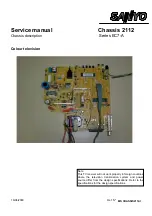
Service manual
CHASSIS 2112-Series EC7-A
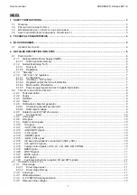
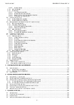
3
7.5
P
OSSIBLE CAUSES OF ENTERING IN PROTECTION MODE
..................................................................................... 27
7.6
P
ROTECTION INHIBITION
. ................................................................................................................................. 27
7.7
F
AILURE LOCATION FLOW
-
CHARTS
. .................................................................................................................. 28
7.7.1
Errors 1, 2 and 6. .................................................................................................................................... 28
7.7.2
Error 3..................................................................................................................................................... 29
7.7.3
Error 4..................................................................................................................................................... 30
7.7.4
Error 11................................................................................................................................................... 30
No error indication. .............................................................................................................................................. 31
8.
GLOSSARY OF TERMS ..................................................................................................................................... 32
1. SAFETY INSTRUCTIONS.
In order to understand correctly this service manual, it should be read along with schematic diagram of model under
study.
All circuits from this chassis, with exception of primary side of power supply, are isolated from mains.
1.1 Warning.
An isolation transformer should be connected in the power line between the receiver and mains when a service is
performed on the primary side of power supply. The deflection heat sink is connected to 12v.
1.2
Precautions against X-Rays.
The primary source of X-RADIATION in the television receiver is the picture tube. The picture tube is specially
constructed to limit X-RADIATION emissions. For continued X-RADIATION protection, the replacement tube must
be the same type as the original including suffix letter. Excessive high voltage may produce potentially hazardous X-
RADIATION. To avoid such hazards, the high voltage must be maintained within specified limit. If high voltage
exceeds specified limits, take necessary corrective action. Carefully, follow the instructions for +B1 volt power
supply adjustment and high voltage adjustment to maintain the high voltage within the specified limits.
1.3
Recommendations to protect our environment.
STAND-BY MODE: In order to save energy and to maintain an optimum picture quality, it is advisable to switch off
the TV using the ON/OFF button located at the front of TV set.
USED BATTERIES: The batteries in the remote control of your TV set do not contain mercury. However, SANYO
recommends that you do not dispose of used batteries in domestic refuse. Please, contact your dealer or your local
authorities for information regarding the disposal of used batteries or your nearest collection point.
RECOMMENDATION ABOUT THE END-OF-LIFE: Your SANYO TV set has been designed and manufactured
using high quality materials which can be recycled and reused. In the future, when the life cycle of this set comes to
an end, specialised companies can disassemble it and reuse certain materials. This reduces the impact of waste in
our environment. Please, contact with your local authorities for information regarding the disposal of your set when
the time arrives. Help us to conserve the environment we live in!.
1.4
Safety and EMC (Electromagnetic Compatibility).
It fulfils the safety requirements established in the regulation: EN 60065:1993.
It fulfils the EMC requirements established in the regulation:
EN 55013:1990/A12:1994
EN 55020:1994
EN 60555-2:1987
Summary of Contents for CE14A2-C
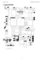
Page 20: ...Service manual CHASSIS 2112 Series EC7 A 5 3 BLOCK DIAGRAM ...
Page 48: ......

