Service manual
CHASSIS 2112-Series EC7-A
10
The microprocessor pins related to the teletext feature are:
•
Video input (CVBS1 signal): pin 34.
•
Teletext PLL adjust voltage: pin 29.
4.2.6.1 Non-interlaced.
When the TV shows the normal TXT situation (black background), the visualisation mode is not interlaced.
When the TV shows the mix/newflash situation (picture on the background), the visualisation mode is interlaced.
The selection between interlaced mode and not interlaced mode is done by an instruction via I2C bus.
4.2.7 –PD
signal.
It is related to an input port. It is active at low level. The power down detector (Q855) actives it.
It indicates that the TV has been switched off and is necessary to start the switch-off process.
4.2.8 ON
signal.
It controls the 8V-regulator output and the 8V regulator controls the 5V-regulator output. So that, if ON=1 there are
8V and 5V, but if ON=0 there are neither 8V nor 5V.
4.2.9
Radio control signals.
A NVM bit indicates whether the radio is mounted or not. It can be modified in the service menu.
The radio management is done by means of four signals:
•
-RADIO (pin 10):
Radio
activation.
•
-R_READ/WRITE (pin 6):
=0
!
read from the radio; =1
!
write to the radio.
•
R_DATA (pin 5):
Data signal radio
"!
micro.
•
R_CLK (pin 4):
Clock signal radio
"
micro.
4.2.10 SC
signal.
It is related to an input A/D converter port. It changes between TV and AV, depending on the pin 8 SCART voltage.
The standard levels at pin 8 SCART are:
From 0V to 3.25V
!
!
!
!
TV
mode.
From 3.25V to 8.25V
!
!
!
!
AV mode, 16/9 format.
From 8.25V to 12V
!
!
!
!
AV mode, 4/3 format.
4.2.11 –SUP_FAIL
signal.
This signal comes from a 5V voltage divider. When –SUP_FAIL is at low level while the ON signal is at high level
means that there is a +8V or +5V failure.
4.2.12 –AM/SCART
signal.
This signal only acts when the IC1401 is present (there is AM sound or radio) because the SCART sound, the AM
sound and the RADIO have the same management into the one chip (IC400).
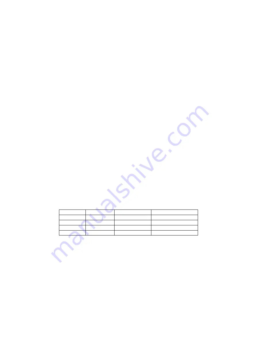
Table of sound commutation:
-RADIO
-AM/SCART
SCART output
AUDEXT ONE_CHIP
L
L
RADIO
RADIO
L
H
AFOUT (IC1400)
RADIO
H
L
AFOUT (IC1400)
AMOUT (IC1400)
H
H
AFOUT (IC1400)
SCART
4.2.13 –LP/L
signal.
Output port. The L’ system is selected when it is at low level and the L system is selected when it is at high level.
4.2.14 –AM/FM
signal.
This signal chooses the IC1400 output signal (AFOUT), selecting AM_IN input when it is 0 or EXT_IN input (that is
the FM signal demodulated by the ONE-CHIP) when it is 1.
4.2.15 –DEFL_FAIL
signal.
It is related to an input port. It is active at low level and managed by the horizontal deflexion protection circuit.
4.2.16 I2C bus and peripherics connected to (SDA y SCL).
All the circuits related to SDA and SCL (pins number 19 and 20 of IC100) signals are the I2C hardware.
The Integrated circuits connected to the I2C are the video processor (IC400) and the non-volatile memory (IC125). The
most of the TV set functions are managed by I2C bus.
4.2.17 CF1 and CF2 signals.
Output signals that manage the sound standard selection (these signals are active at low level). CF1 selects the
CF202 filter and CF2 selects the CF201 filter.
4.2.18 Tuning control signals (-AGC_LS, -LB, -MB, -HB, VTUNE).
The signals - LB (band VL), - MB (band VH), - HB (band U) are outputs active at low level, they select the tuning
bands.
Summary of Contents for CE14A2-C
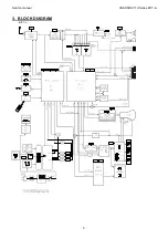
Page 20: ...Service manual CHASSIS 2112 Series EC7 A 5 3 BLOCK DIAGRAM ...
Page 48: ......

