Service manual
CHASSIS 2112-Series EC7-A
13
4.3.7.3
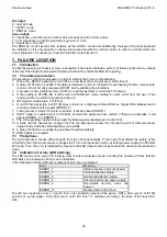
Beam current overconsumption protection.
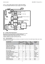
The overconsumption of beam current (when there is a short-circuit to ground, for example) provokes that the BCI
signal decrease underneath 0V permanently, entering in conduction D504 and D505. This provokes that –
DEFL_FAIL signal resets to low level.
4.3.7.4
C656 open-circuit protection.
If C656 is opened, the final result is the EHT voltage goes up until a dangerous level that can damage both the FBT
and the tube. The circuit formed by Q611 and its periphery carries out short-circuiting the
V_GUARD signal to
ground when flyback pulses, at central point of the diode modulator get over a certain peak level. In this case,
ERROR_2 is shown.
4.4 Vertical
deflection.
The amplifier of vertical deflection is the integrated circuit LA7840L.
The output signal that comes from IC400 (balanced, +V_DRIVE and -V_DRIVE signals) is applied to R711, R712
and to the outputs of IC701. Later, it is amplified by IC701 and applied to the deflection coil.
R702 the sensing resistor. It is a Metal Film resistor in order to give stability in temperature and to avoid the drifts.
Its value defines the height and it is optimised for each tube. Resistors R711 and R712 define also the height. In
case of changing anyone of these three resistors, they should be replaced by the same type as they are.
R705 is the damping resistor of the deflection coil.
The amplifier is the DC coupler (there is no coupling capacitor), therefore to achieve that the deflection coil current
conducts in both sides, the supply of IC701 must be symmetrical. The advantage of the DC coupler is avoiding the
linearity N/S mistakes (consequently, there is no linearity N/S adjustment).
4.4.1
Vertical deflection suppliers.
There are two power supply voltages for the vertical deflection:
+12
!
!
!
!
it is used to give current to the top half of the screen.
- 12
!
!
!
!
It is used to give current to the bottom half of the screen.
To generate the flyback pulses, it is used the pump-up circuit of voltage integrate in IC701. It allows flyback levels of
38V in the outputs from a symmetrical power supply of 12V.
4.4.2
Vertical deflection protection.
Whenever there is a failure in the vertical deflection circuit that is a danger, the vertical flyback disappears.
The vertical flyback is fed back towards pin 22 of IC400 by means of V_GUARD signal. In the case of lacking the
pulses of vertical flyback, the video processor (IC400) activates a bit that is checked through bus I2C by the
microprocessor, periodically.
When the reading indicates anomaly, the microprocessor shows ERROR_2.
The vertical protection is disabled in these cases:
#
V-STAT or I2C BUS is selected in service mode.
#
The TV set is in standby mode.
#
During the switch on / off transients of TV set.
#
In forced switch on mode.
4.5
Beam current limiter and geometry compensations.
4.5.1
BCl signal generation.
Signal BCI reflects the beam current of the tube. The absence of beam current causes that in BCI there is a voltage
near 8V. The greater is the beam current, the less is the BCI voltage. This information is used for the geometry
compensations, as well as for the ABL.
The time constant of BCI signal should be around 0,5mS so that it can be used in the geometry compensations. In
order to be able to obtain this time constant (quite fast), the connection of the return path from the CRT (aquadag)
is connected to BCI signal. Therefore, the CRT aquadag is not ground.
4.5.2 Geometry
compensations.
4.5.2.1
Width and height compensation.
Through R425 BCI signal is taken to pin 50 of the video processor (IC400).
The compensation of height is made varying the amplitude of +V_DRIVE and - V_DRIVE signals, according to the
voltage level in IC400 pin 50.
The compensation of width takes place by means of the diode modulator. With greater beam current, the voltage
between terminals of C673 decreases, being in a reduction of the width that compensates the increase produced by
the reduction EHT voltage.
4.5.2.2 Phase
compensation.
Due to variations in the beam current, the horizontal flyback width changes. The video processor dispose of a
phase comparator to correct the position of the image in the screen due to variations in time of storage of line
transistor, but it is not able to compensate the variations in the width of horizontal flyback. This causes distortions in
the picture due to phase deviation.
Though R416 the BCI signal is taken to pin 42 from the video processor (IC400). In this pin, the capacitor is
connected to give the time constant in the second phase comparator. Extracting current from this pin, the picture
Summary of Contents for CE14A2-C
Page 20: ...Service manual CHASSIS 2112 Series EC7 A 5 3 BLOCK DIAGRAM ...
Page 48: ......


