Service manual
CHASSIS 2112-Series EC7-A
16
4.7.1.5
Video filter and switches.
In video filters and switches block, there are the following sections:
#
Video signals selector.
#
Filter
calibrator.
#
Chroma band-pass filter and automatic colour control.
#
Chroma
trap.
The video signals selector selects the video inputs (pin 13, CVBS_INT; pin 17, CVBS_EXT; pin 11, CVBS/Y and pin
10, CHROMA). The selection is made by the microprocessor via I2C. The selected video is sent for further
processing (filters), at the same time it outputs at pin 38 (CVBSO).
The filter calibrator is a circuit that calibrates the filters each frame retrace. The calibrated filters are the chroma
band-pass filter and the luminance trap.
The selected video signal is sent to the chroma band-pass filter via an amplifier whose gain is variable and it is
controlled by the automatic colour control. The information input for the automatic colour control is the chroma burst
signal. The circuit maintains the colour saturation in different amplitudes of chroma. The band-pass filter output is
applied later to the colour decoder.
The selected video signal is also sent to the chroma trap. When coming out of the chroma trap there is the
sharpness block (peaking) and noise filter (coring), that are programmed by the microprocessor via I2C. The output
signal resulting is sent to pin 28 (LUMOUT), where there is applied a band-pass filter formed by L404, R428 and
C422. Both the chroma trap and the band-pass filter are disabled when the signal has a Y/C form (coming from a S-
VHS video).
4.7.1.6 Colour
decoder.
In the colour decoder block, there are the following sections:
#
PLL/VCXO.
#
PAL/NTSC
demodulation.
#
SECAM
demodulation.
#
System automatic management.
The PLL works during the burstkey time lapse. It generates a VCXO reference signal, which is in phase locked to
the chroma burst of the selected video signal. For this, it is used the quartz crystal (X400) connected to pin 35. The
components related to PLL circuit are the connected one to pin 36 (DET).
The reference signals coming from VCXO are supplied to the phase rotator (hue control), and later both supplied to
the R-Y and B-Y demodulator and to the colour identifier. The band base signals R-Y y B-Y is taken to the delay
line via PAL/SECAM switcher. The output of the delay line goes to pins 30 (RYO) and 29 (BYO).
The SECAM demodulation is carried out with a PLL demodulator. The reference voltage, generated in pin 16
(SECPLL), is regulated so that the PLL demodulator output is set at a reference voltage generated internally. Being
outside the calibration, the oscillator tracks the SECAM chroma, giving as a result the corresponding demodulated
signal. The base band signals R-Y and B-Y are taken to the delay line via PAL/SECAM switcher. The system
automatic manager identifies what kind of chroma is being demodulated. Its output is accessible for the
microprocessor via I2C.
4.7.1.7 RGB
processing.
In RGB processing block, there are the following sections:
#
Dematrixing R-Y / B-Y.
#
RGB
selector.
R-Y / B-Y signals are taken to two amplifiers whose gain is programmed by the microprocessor via I2C (colour
control by the user). The outputs of these amplifiers are taken along with the Y signal to the matrix, where the RGB
signals come from.
The RGB selector is controlled by the FB signal, which enters through the pin 26 (RGBIN). The RGB selection is
made between the RGB matrix outputs and the inputs of external RGB (pins 23, RI; 24,GI; 25,BI). The RGB
selector output is taken to the RGB control.
4.7.1.8 RGB
control.
In RGB control block, there are the following sections:
#
Contrast
control.
#
Brightness
control.
#
Beam current limiter and vertical protection.
#
Cathode self-calibration (AKB).
#
Amplitude excursion adjustment and white control.
The RGB signal that comes from the RGB selector goes to Contrast and Brightness control blocks, which are
programmed by the microprocessor via I2C (user control). The output of these blocks is given to the cathode
calibration block (AKB). Both controls can be shorten by the beam current limiter. The pin 22 (BCLIN) is input with
double function: during the vertical retrace is a vertical protection input and during the sweeping it is a beam current
limiter.
If during the vertical retrace there is a level less than 3,7V, the video processor understands that there is a vertical
failure and then the video processor considers there is a vertical failure and it activates a bit that is read by the
microprocessor via I2C.
Summary of Contents for CE14A2-C
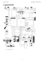
Page 20: ...Service manual CHASSIS 2112 Series EC7 A 5 3 BLOCK DIAGRAM ...
Page 48: ......

