Service manual
CHASSIS 2112-Series EC7-A
17
During the sweeping, the resting voltage is 3.4V. The ABL circuitry (formed by Q673 and their periphery) reduces
this voltage if it is necessary. The contrast reduction begins when the voltage of pin 22 (BCLIN) is lower than 3V.
The brightness reduction begins when the voltage of pin 22 (BCLIN) is lower than 2V.
#
Cathode self-calibration (AKB)
is carried out by means of two point’s stabilisation loop. A stabilisation point is
the black level one (cut-off, polarisation) and the other is the white level one (gain). Each cathode is calibrated
sequentially and independently. The stabilisation of the black level and the white level takes place in alternating
fields (black - white - black - white…). The system feedback signal enters through the pin 18 (BLKIN). Through
this pin enter the cathode current, which is supplied by the RGB amplifier by means of AKB line.
#
Black level stabilisation (polarisation):
Before the blanking field, three pulses are inserted sequentially in
RGB outputs (a pulse in each line). A servomechanism adjusts the polarisation of RGB outputs until obtaining
that 8uA enters in each of the three pulses through pin 18.
#
White level stabilisation (gain):
After the blanking field, three pulses are inserted sequentially (a pulse in each
line). Another servomechanism adjust the gain of three amplifiers (R, G, B) so that it stabilises a reading of
20uA (BLKIN) in the three pulses through pin 18. It implies that the cathodes final excursion does not depend
on the gain of the RGB final amplifier. The excursion adjustment of cathodes is made changing the amplitude of
RGB signal along with the sensing pulses. The microprocessor writes via I2C an adjustment that determines
this amplitude and it has the same effects in the three amplifiers (K-DRV in Service mode). In the same way,
but independently for each channel, the adjustment of the white balance is made. The microprocessor writes
via I2C three adjustments that affect independently to each one of the three colours. The adjustment of G and B
is accessible in way service (the red one is prefixed to a certain value).
#
Tube start-up:
When the TV set starts to work, the microprocessor monitorises, via I2C, a bit that indicates
whether the servo is stable (it only will be stable when there is cathodes transmission, that is to say, when the
heaters are hot and the polarisation G2 is right). When the servo is stabilised, a picture is shown up.
4.7.1.9
Supply and Bandgap.
The supply is 8V and enters by pins 12 (VP1) and 37. The ground pins are the 14 and the 44 ones. Internally a
stabilised voltage is generated in temperature. This supply is called “Bandgap”, and its decoupling is the
components connected to pin 9 (DECBG).
4.7.2
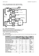
Block diagrams of video paths.
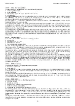
#33
#34
IC100 (ST92195)
TXT
Y/CVBS-IN
CVBS-OUT
CHROMA
S900
S901
#38
#6
#17
#13
#11
#10
IC400 (TDA884X)
VIF
TRAPS
CVBSEXT
CVBSINT
Y
C
Σ
4.8
Audio signal processing.
4.8.1 Audio
processor.
The audio processor is integrated along with the video processor IC400. This component is controlled by the
microprocessor (IC100) by means of the I2C bus. Some of the basic functions, the audio processor carries out,
are:
•
Demodulation of IF audio signal. The band-pass filter must be connected externally. The audio signal outputs
through a limiter circuit and it is demodulated by means of a PLL, which auto-tunes automatically to the carrier
of the output signal. It is not necessary carry out any adjustment. This demodulation is only possible for FM
sound.
•
The volume control is made by means of I2C bus.
•
The deemphasis output gives an audio signal with a fixed level. It needs an external capacitor (C407).
In addition, for TV sets with standard of AM sound the audio signal must be demodulated externally.
4.8.2 AM
sound.
Only for models with standard L.
Summary of Contents for CE14A2-C
Page 20: ...Service manual CHASSIS 2112 Series EC7 A 5 3 BLOCK DIAGRAM ...
Page 48: ......

