Service manual
CHASSIS 2112-Series EC7-A
19
0
1
Depends on
the tuner
signal system.
RADIO
RADIO
Tuner
0
0
X
RADIO
RADIO
RADIO
4.8.5 Speaker
amplifier.
The speakers amplifier is based on the integrated circuit TDA7233S (IC300). It is the amplifier of one channel,
supplied by B2 and with a gain fixed by resistor divider R319/R316. The power supplied is approximately 1Wrms at
10% distortion
.
The input (pin 4) comes from the audio processor (IC400). The power output for the speakers is in pin 1.
A mute is performed in this IC by unbalancing its output. When the MUTE line, coming from the microprocessor, is
a high level the voltage at pin 3 of the amplifier is bigger than the internally fixed level, with which the output remains
unbalanced
.
This mute is only used when TV set is switch on or off and when some times there is a bad reception
of TV signal, with the purpose of avoiding noises. Under any other circumstances, the audio processor, IC400,
carries out the mute function.
4.9 RGB
amplifier.
It is a class ‘A’ configuration carried out with the transistors Q501, Q502 and Q503. Q570 and the divider, formed by
R571 and R572 carry out the voltage reference for the amplifiers. The reference voltage is 1,8V. The amplifiers
supply is the voltage B3, generated in the FBT. The transistors Q511, Q512 and Q513 sink the current from each
cathode towards a common point. The sum of all these currents is conducted through the line AKB toward the
processor of video where will be measured. The video processor compensates the possible variations in the chain
of RGB, modifying the exits of RGB. More details see the chapter ‘Video processor’.
4.10 CRT socket connector.
The tubes can have internal discharges; they go from the anode (EHT) to any other terminal of CRT (Focus, G2,
G1, cathodes or heaters). This phenomenon is most frequently when the tubes are new and it tends to disappear
when the TV set has already worked during a time.
As a main measure to protect against the internal discharges, spark-gaps are incorporated into each terminal of the
tube. These spark-gaps are located into the CRT socket. Its goal is conducting the biggest part of the discharge
towards the aquadag of the tube, so the current goes by shortest and direct way.
There are several types of CRT socket in the market. The differences between them can be in the spark-gaps
position. That is why it is obvious to stand the importance out that if it is necessary to replace this connector, it will
be used as a spare part what is in the components list of model.
The repercussions of mounting a wrong CRT socket are:
#
Possible failure in CRT in case of discharge.
#
Possible failure of chassis in case of discharge.
#
Possible reduction of contrast due to a short-circuit of BCI signal with another points.
4.11 Peripheral connections to TV set.
Possible configurations of peripherics and their recommended connection to Scart and frontal RCA of the TV set
are detailed.
Scart
Front
Decoder C+
VCR, S-VCR
SAT
Receiver
HI-FI
Video
Video
Games
Video
Camera
Video
Games
5. CONFIGURATION AND ADJUSTMENTS.
5.1 Service
menu.
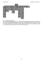
In order to accede to the service menu, press the key Vol – from TV local keyboard, and simultaneously pressing
the green key or 2-digits key (-/--) from the remote control. There are the following options in this menu:
Summary of Contents for CE14A2-C
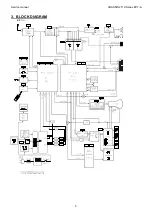
Page 20: ...Service manual CHASSIS 2112 Series EC7 A 5 3 BLOCK DIAGRAM ...
Page 48: ......

