Service Manual SM CE14A2-C
3
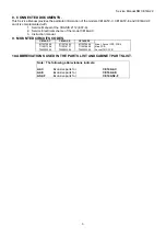
8. CONNECTED DOCUMENTS.
This Service Manual provides the particular information of the models CE14AT2-C, CE14AT2-E and CE14AX2-F
and it is complemented with:
1. Service Manual of the CHASIS 2112 (EC7-A).
2. Service Electrical scheme of the model CE14A2-C.
3. Instruction
manual.
9. MOUNTED CIRCUITS CODES.
CE14A2-C
CE14A2-E
CE14AS2-F
6110372809
6110375802
6110375604
Main + Socket TRC PCB’s
7110017204
7110018707
7110018608
Main PCB
7040003506
7040003506
7040003506
Socket TRC PCB
10. ABBREVIATIONS USED IN THE PARTS LIST AND CABINET PARTS LIST.
Note : The following abbreviations indicate:
A2-C
Exclusive parts for
CE14A2-C
A2-E
Exclusive parts for
CE14A2-E
AS2-F
Exclusive parts for
CE14AS2-F
Summary of Contents for CE14A2-C
Page 20: ...Service manual CHASSIS 2112 Series EC7 A 5 3 BLOCK DIAGRAM ...
Page 48: ......


