Service manual
CHASSIS 2112-Series EC7-A
26
First digit:
‘0’: normal mode
‘1’: HOTEL mode
‘2’: RENTAL mode
Second digit:
‘0’: It switches on into the same channel as it was switched off (normal mode).
‘1’ to ‘8’: It switches on into the selected programme (1 to 8).
‘9’: It switches on into AV1
The ‘RENTAL’ mode has the same features as the ‘HOTEL’ mode and, additionally, the keys of the local keyboard
are inhibited, so it is only possible to change the programme with the remote control. In order to quit this mode, the
colour saturation, it is necessary to set the saturation colour level to 0.
7. FAILURE LOCATION
7.1 Introduction.
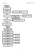
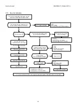
So that the repairing of chassis is more reasonable, it has been included a system of failure signal code by means
of the led. This diagnosis along with the failure location flow-charts facilitate its repairing.
7.2
The start-up procedure.
The procedure of the microprocessor in order to start-up the TV set is the following:
1. When the –RESET signal (pin 2 of IC100) is a low level, the microprocessor starts to work.
2. A delay of 750msec. is added. This delay is included in order to minimise the overheating of some components,
in case of short-circuits provokes a RESET before enabling the protections.
3. It accedes to non-volatile memory (IC125) to read the last state in which the TV set was.
4. If the reading is STAND_BY, it will remain in STAND_BY mode, waiting for some order from the user. If the
reading is ON, the start-up procedure will go on.
5. ON signal is enabled (pin 3 of IC100)
6. If –SUP-FAIL signal (pin 9 of IC100) does not raise to a high level before 200msec. Signal ON is disabled and it
is shown a failure of the supply (ERROR_4)
7. Video processor starts. If there is no answer, it will be shown ERROR_1.
8. HOUT signal is enabled (pin 40 of IC400), at which the deflections are started. If there are anomalies, it will
appear ERROR_2 or ERROR_3.
9. The corresponding channel is tuned and the Mute signal is disabled (pin 52 of IC100).
10. It waits until the heaters are enough hot. The microprocessor knows it by monitoring a bit of video processor
related to the Cathode self-calibration servo (AKB).
11. A delay of 500msec. is added to guarantee the picture stability.
12. RGB signals are enabled.
7.3 Protections.
The microprocessor checks different parts from the circuit periodically. If some part that affects the safety of the
circuit fails, then the microprocessor changes the TV set into protection mode, by setting power supply into STAND-
BY mode. Then, the error is indicated by means of the LED (reason) that it has caused the entrance into protection
mode.
7.4
Indication of errors (LED blinking).
The LED carries out a cycle of N blinking when it enters protection mode. Counting the number of times that the
LED blinks, the indication of Error can be identified.
In the following table the different conditions of error are enumerated:
Error
Meaning
ERROR_1
Video processor does not answer
ERROR_2
Vertical deflection failure.
ERROR_3
Horizontal deflection failure.
ERROR_4
Short-circuit into the power supply.
ERROR_6
Non-volatile memory does not
answer
ERROR_11
General failure of I2C bus.
The I2C bus reads the errors 1, 2 and 6. Error 3 is enabled by means of the signal - DEFL_FAIL (pin 14 of IC100)
and error 4 by the signal - SUP_FAIL (pin 9 of IC100). Error 11 enables according to the state of the lines SDA,
SCL.
Summary of Contents for CE14A2-C
Page 20: ...Service manual CHASSIS 2112 Series EC7 A 5 3 BLOCK DIAGRAM ...
Page 48: ......

