Service manual
CHASSIS 2112-Series EC7-A
28
7.7
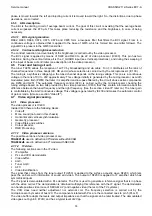
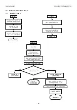
Failure location flow-charts.
7.7.1
Errors 1, 2 and 6.
ERROR_1
Check the +8V at pins
12 and 37 of IC400
Check the continuity of I2C but
path to pins 7 and 8 of IC400
OK
Change IC400
OK
Switch on the TV set wit M key
pressed (inhibited protections)
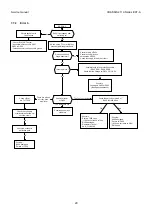
ERROR_6
Check +5VM at pin 8 of IC125
Change IC125
Check the continuity of I2C bus
to the pins 5 and 6 of IC125
OK
OK
Check C656
Check C700 and D701
Change IC701
YES
NO
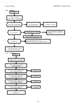
ERROR_2
Check the vertical
deflection path to IC701
Switch on the TV set with PL103 key
pressed (inhibited protections)
Increase G2 just to light the screen
Does picture spread over
the whole screen?
Check the path of
V_GUARD signal
Check the ramp generator
(pin 51 of IC400)
Possibly:
* C425 damaged
*IC400 damaged
Check +V_DRIVE and -VDRIVE
signals at pins 4 and 5 of IC701
Check -12 and +12 at pins 1 and 3 of IC701
Summary of Contents for CE14A2-C
Page 20: ...Service manual CHASSIS 2112 Series EC7 A 5 3 BLOCK DIAGRAM ...
Page 48: ......

