Service manual
CHASSIS 2112-Series EC7-A
29
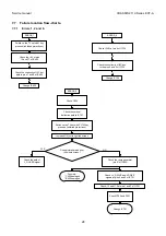
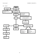
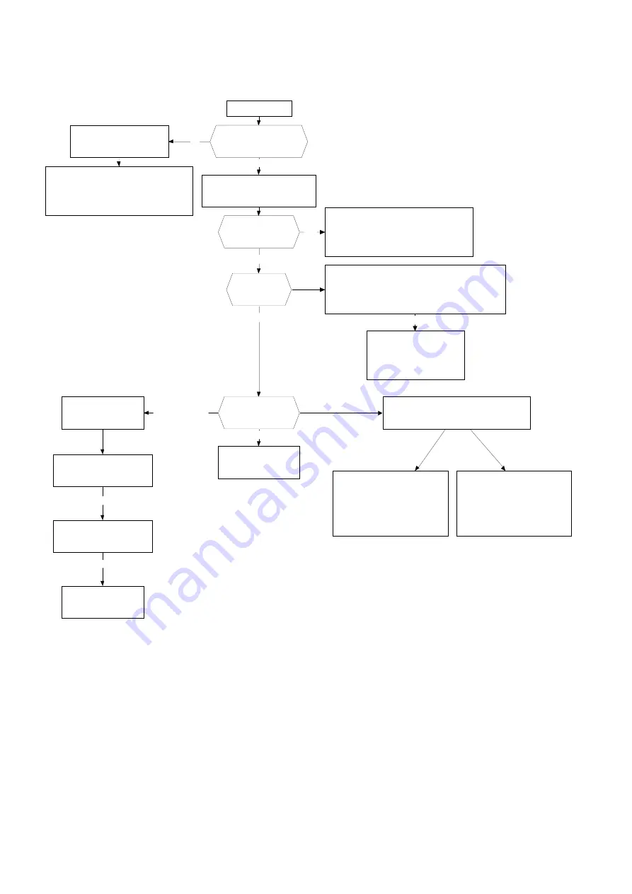
7.7.2 Error
3.
ERROR_3
Picture appears with
flyback lines
*Check +B3 at CRT socket.
*A possible short-circuit in Q501,
Q502 or Q503
*Cathode possibly short-circuit to ground
Switch on the TV set with M key
pressed (inhibited protections)
Does it just happen after
switching on?
Check the continuity
of horizontal deflection coil
until the circuit
Does it sound line
stage abnormal?
* Possible faulty of T650
* Possible short-circuit on
secondaries of T650
* Check the supply of the driver circuit
Possibly:
*X400 damaged
*Failure of T650
OK
OK
No
Yes
No
Yes
No
Possible short-circuit
of heaters
The pulses are OK
Possibly:
Leakage in C402 or C403
(Bandgap capacitance)
OK
Check the horizontal
deflection path
Possible faulty in the protection circuits
(D562, D561, D504, D505)
Check that the voltage at -DEFL_FAIL is 5V.
Check the patch from pin 40 of
IC400 to Q600 base
Bad
Possibly:
*X400 damaged
*Failure of IC400
*+8V does not reach to Q601
*R418 open
Possibly:
*Primary T600 open
* +12 does not reach to T600
*Q600 damaged
*Generator circuit of
de H_FLY&SYNC
Check +B1 at
pin 7 of T650
Is there picture ?
Check collector
of Q600
There are pulses
but they have
a low level
OK
There are not pulses
Summary of Contents for CE14A2-C
Page 20: ...Service manual CHASSIS 2112 Series EC7 A 5 3 BLOCK DIAGRAM ...
Page 48: ......

