background image

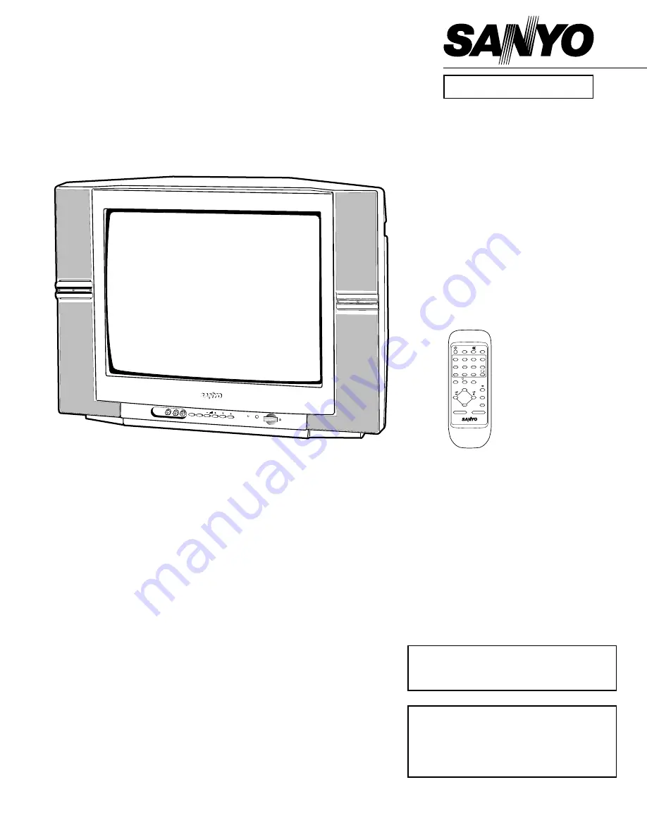
SERVICE MANUAL   Colour Television   

Product Code: 111358219

Original Version

Chassis Series: AC5-G1

C4VZ

FILE NO.

Model No. CP21KX2

(A)

Service Ref. No. CP21KX2-50

(Australia)

Give complete “SERVICE REF. NO.” for
parts order or servicing. It is shown on the
rating plate at the cabinet back of the unit.

This T.V. receiver will not work properly in 
foreign countries where the television
transmission system and power source dif-
fer from the design specifications. Refer to
the specification table.

REFERENCE NO.

SM

5110601

0

7

1

4

8

5

2

3

6

9

P

P

JXMYA

-/--

P

P

TV/AV

A B

CH SCAN

TIMER

MENU

PIC MODE

SWAP

BASS

SURROUND

VIDEO

L-AUDIO-R

TV/AV MENU

CH

Specifications

Power Source  . . . . . . . . . AC110-240V, 50Hz/60Hz.
Colour System   . . . . . . . . PAL/NTSC4.43/NTSC/PAL-60Hz
Television System   . . . . . . B/G, D/K, K’, I, M/M
Channel Coverage   . . . . . VHF: 0-11, 5A (Aus.), 1-11(NZ), 

E2-E12, R1-R12, K1-K9, A2-A13, J1-J12

UHF: 21-69, A14-A69, J13-J62
CATV: S1-S41, X, Y, Z, Z+1, Z+2

Video IF . . . . . . . . . . . . . . 38.0MHz      
Aerial Input Impedance   . . 75

Ext. Terminals

Video inputs: Phono jack 

✕ 

2 (1Vp - p, 75

Ω)

Audio inputs: Phono jack(L/R) 

2(436mVrms, more than 40K

Ω)

Video monitor outputs: Phono jack 

1(1Vp - p, 75

Ω)

Audio monitor outputs: Phono jack (L/R) 

1(436mVrms, less than 600

Ω)

Sound Output (RMS)  . . . . 5W + 5W
Speaker

 . . . . . . . . . 6 cm 

✕ 

12 cm 

2 pcs.

Dimensions

 . . . . . . . . . 625 (W) 

461 (H) 

✕ 

484 (D)mm 

Weight

 . . . . . . . . . approx. 21.2 Kg

Specifications subject to change without notice.

Summary of Contents for CP21KX2

Page 1: ...V A B CH SCAN TIMER MENU PIC MODE SWAP BASS SURROUND VIDEO L AUDIO R TV AV MENU CH Specifications Power Source AC110 240V 50Hz 60Hz Colour System PAL NTSC4 43 NTSC PAL 60Hz Television System B G D K K I M M Channel Coverage VHF 0 11 5A Aus 1 11 NZ E2 E12 R1 R12 K1 K9 A2 A13 J1 J12 UHF 21 69 A14 A69 J13 J62 CATV S1 S41 X Y Z Z 1 Z 2 Video IF 38 0MHz Aerial Input Impedance 75Ω Ext Terminals Video in...

Page 2: ...ON PRECAUTION The primary source of X RADIATION in television receiver is the picture tube The picture tube is specially con structed to limit X RADIATION emissions For continued X RADIATION protection the replacement tube must be the same type as the original including suffix letter Excessive high voltage may produce potentially hazardous X RADIATION To avoid such hazards the high voltage must be...

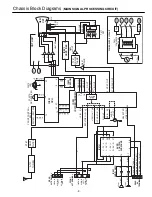
Page 3: ... VIDEO MONITOR OUT AUDIO MONITOR OUT LEFT AUDIO MONITOR OUT RIGHT 46 44 VIDEO OUT INT VIDEO IN 42 VIDEO IN AUDIO IN LEFT AUDIO IN RIGHT SP901 IC001 AUDIO AMP 2 6 AUDIO CONTROL SURROUND 10 1 AUDIO TV OUT 26 5 1 30 L OUT SP902 12 8 21 R OUT 52 54 SIF OUT SIF IN RGB MATRIX 19 20 21 OSD R OUT OSD B OUT OSD G OUT OSD R IN OSD B IN OSD G IN 14 15 16 180V 9V L OUT R OUT REAR AV TERMINAL FRONT AV TERMINAL...

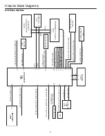
Page 4: ...ve High OSD BLUE OUT Active High DEFLECTION CIRCUIT HORIZ SYNC IN ACTIVE LOW VERT SYNC IN ACTIVE LOW POWER PROTECT IN POWER ERROR LOW POWER CIRCUIT etc SCL SDA IC802 MEMORY OSC X801 32 768KHz CPU OSC OUT CPU OSC IN LED ON TIMER LED OUT ON TIMER ON Low RC SIGNAL IN ACTIVE HIGH RC PRE AMP 9 30 SOUND VOLUME OUT IC001 AUDIO AMP VIF M OUTPUT HIGH NTSC LOW OTHER A101 F S TUNER AFT SIGNAL INPUT 10 RESET ...

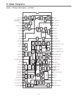
Page 5: ...LMP V C VCC 5V 46 47 48 49 50 A2C PLL 51 52 53 54 Audio Output FM Output Selected Audio Output PIF AGC RF AGC Output PIF Input1 PIF Input 2 IF Ground IF Vcc FM Filter AFT Output Bus Data Bus Clock ABL Red Input Green Input Blue Input Fast Blanking Input RGB Vcc Red Output Green Output Blue Output fsc output or C Sync output Vertical Output Ramp ALC Filter Horizontal BUS Vcc Horizontal Output Horiz...

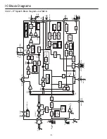
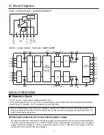
Page 6: ... 3bit Amp 54 10p SIF In Sound BPF VCO Coil VCO COIL1 VCO COIL2 48 49 VIF VCO Chroma Counter B N INV IF Ident OSC C D Amp SIF Sys 2bit pre scaller SIF VCO 500K BPF SIF APC Filter 1K 0 01u 1000p 53 LIM AMP FM Det FM Level 5bit Chroma C D APC Det 500K Det To BUS Chroma VCO VIF Counter Reset Pulse VCO Ident VIF Sys 2bit Phase Detector A MUTE 1bit VOLUME D A VOLUME Filter A SW 1bit Input Select VOLUME ...

Page 7: ...ply lines Releasing the protective circuit and restoring power supply To release the protective circuit and restore power supply turn the power to the TV set OFF and then ON again via either the main power switch or the ON OFF button on the remote control This will work only if the power supply trouble was temporary If there is permanent trouble such as a damaged circuit power cannot be restored a...

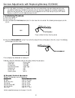
Page 8: ... on the TV set while the above On Screen Display is still on the screen The following picture appears on the screen This completes the initialization of memory IC Following shows the initialized contents of memory data by this procedure Plug play No executed Inhibit data Cancelled Ch skip data Cancelled Sound volume data 10 63 steps Volume Lock OFF Tuning Lock OFF Colour system AUTO 1 CLR Press an...

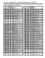
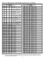
Page 9: ...hows the initial values which have been stored in the CPU ROM and items for the service adjustments Service mode adjustments table in CPU ROM DATA INITIAL No ITEM RANGE SETUP SCRIPTION DATA 43 PORS 0 3 2 Pre shoot Over shoot Adj in AV mode 44 RFCO 0 3 0 RF Coring Gain Adj 45 PORWN 0 1 0 Switching of RF Pre shoot and Over shoot 46 PORSN 0 3 0 RF Pre shoot Over shoot Adj 47 TINT 16 15 0 RF Tint Adj ...

Page 10: ...1 ROM Correction 318 R18 0 255 236 ROM Correction 319 R19 0 255 141 ROM Correction 320 R20 0 255 235 ROM Correction 321 R21 0 255 141 ROM Correction 322 R22 0 255 33 ROM Correction 323 R23 0 255 155 ROM Correction 324 R24 0 255 6 ROM Correction 325 R25 0 255 33 ROM Correction 326 R26 0 255 154 ROM Correction 327 R27 0 255 246 ROM Correction DATA INITIAL No ITEM RANGE SETUP DESCRIPTION DATA 328 R28...

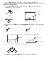
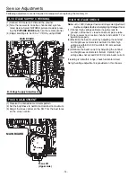
Page 11: ...tion adjustment Read Status Item No Item Data value Display for RF AGC RF AGC adjustment Read Status Item No Item Data value Data value for Red Display for DRV White balance adjustment Read Status Item No Item Data value for Blue To return to normal TV mode press the MENU button on the TV set or the remote control handset 2 Select item by pressing the TIMER Item No UP or SOUND MUTE Item No DOWN bu...

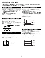
Page 12: ... a monochrome circular pattern 2 Set the brightness and contrast to maximum 3 Select V SIZ in the service mode 4 Change value to be optimum vertical size 5 Exit from service mode Item 04 V SIZ VERTICAL SIZE 1 Receive a crosshatch pattern 2 Select a picture mode of NATURAL by pressing the PICTURE MODE button 3 Select V SCO in the service mode 4 Adjust Vertical S letter Correction so that the differ...

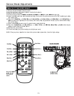
Page 13: ...and turn the screen volume on the FBT to obtain just visible one coloured line 6 Press the 1 Red Bias 2 Red Bias 5 Green Bias 6 Green Bias 9 Blue Bias or 0 Blue Bias button to adjust the brightness of each colour until a dim white line produced Please see the control button alloca tions in this mode 7 Select Item 21 DRV mode to enter the white balance adjusting mode 8 Press the 3 Red Drive 4 Red D...

Page 14: ...R613 H2 C608A R628 R629 R617 C611A C629 C225 R643 C646 D663 J666 D662 R669 C610 J607 R613Z R613Z H2 R613Z H1 Q615 R621 D618 R622 Q616 R624 R623 C615 T611 R616 J608 Q613 H1 C632 J632 C645 J655 Q613 Q613 H T611 H14 T611 H10 T611 H2 T611 H4 T611 H7 T611A Q613 H3 Q613 H2 Q613 H5 Q613 H4 J609 JP641 R525 D619 D616 J634 D6 32 JP632 D694 R631 C635 D507 Q635 Q686 T611 H11 T611 H13 T611B VERT OUT B ADJ 14 S...

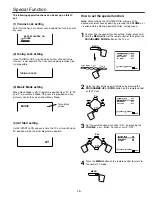
Page 15: ...essing the VOLUME or button To cancel set to OFF 2 Tuning Lock setting The following special functions can be set up on this TV set With this function a maximum sound volume limit can be set at any level 3 Music Mode setting When Music Mode is ON Programme position from 91 to 99 and 0 are set Music Mode Only sound is provided and any picture is not on the screen under Music Mode Set AV START to ON...

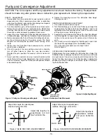
Page 16: ...olours to check this use bias controls Readjust the yoke position if necessary until all screens are pure 7 Adjust each Bias control and screen control to obtain white raster Refer to Gray Scale Adjustment If part of the picture screen is coloured adjust the Deflection Yoke position forward or backward slightly 8 Tighten the mounting screw of the Deflection Yoke Adjust Convergence next CENTRE CONV...

Page 17: ...C4VKR 4 610 311 0790 CABINET FRONT C4VZ 5 645 040 4672 BADGE SANYO or 645 041 7269 BADGE SANYO 6 610 307 3248 DEC SPEAKER C4VKR 7 610 311 0851 CABINET BACK C4TS 8 610 313 0262 LABEL RATING PAL SMALL 9 610 256 7670 HOLDER AC CORD SGP D4VA 10 645 054 3579 ASSY REMOCON JXMYA 11 610 300 5102 RC BATTERY LID 610 313 1009 INSTRUCTIONS MANUAL C5ZY A Key No Part No Description Key No Part No Description 8 ...

Page 18: ...ed when a component replacement is made in any area of a receiver Components indicated by a mark in this parts list and the circuit diagram show components whose value have special significance to product safety It is particularly recommended that only parts specified on the following parts list be used for components replacement pointed out by the mark Note Parts order must contain Service Ref No...

Page 19: ... TR 2SC2412K T146 R 405 014 4608 TR 2SC2412K T146 S 405 015 8704 TR 2SC2812 L6 TB 405 015 8902 TR 2SC2812 L7 TB 405 173 9803 TR 2SC3928A1R 405 173 9902 TR 2SC3928A1S Q686 406 000 6804 TR 2SA1015 G SAN TPE2 405 001 7407 TR 2SA1015 O SAN 405 001 7605 TR 2SA1015 Y SAN 405 004 3109 TR 2SA564A Q CU 405 004 3208 TR 2SA564A R CU 405 006 1707 TR 2SA933S Q 405 006 1806 TR 2SA933S R Q861 405 134 5905 TR 2SA...

Page 20: ...33U J 50V C232 403 260 2904 MT COMPO 0 33U J 50V C233 404 084 8400 ELECT 1000U M 25V 403 045 1504 ELECT 1000U M 25V C234 403 215 2201 CERAMIC 0 01U K 50V C243 403 215 2201 CERAMIC 0 01U K 50V C244 404 084 9308 ELECT 47U M 50V 403 051 3103 ELECT 47U M 50V C245 404 084 9803 NP ELECT 1U M 50V 403 086 2300 NP ELECT 1U M 50V C246 404 084 8806 ELECT 1U M 50V 403 049 0008 ELECT 1U M 50V C247 404 084 9001...

Page 21: ...502 ELECT 470U M 35V C644 404 084 8400 ELECT 1000U M 25V 403 045 1504 ELECT 1000U M 25V C645 404 088 6600 ELECT 2200U M 25V 403 045 9807 ELECT 2200U M 25V C646 404 087 6007 ELECT 47U M 35V 403 054 0703 ELECT 47U M 35V C647 403 303 6104 ELECT 2 2U M 50V C651 404 084 7601 ELECT 470U M 10V 403 041 4509 ELECT 470U M 10V C661 404 084 8905 ELECT 10U M 50V 403 049 4204 ELECT 10U M 50V C662 404 084 8004 E...

Page 22: ...AZE 33K JA 1 16W R3702 401 105 4601 MT GLAZE 3 9K JA 1 16W R3725 401 105 4205 MT GLAZE 33K JA 1 16W R3726 401 105 4601 MT GLAZE 3 9K JA 1 16W R3731 401 105 0405 MT GLAZE 100 JA 1 16W R3732 401 105 0405 MT GLAZE 100 JA 1 16W R422 401 020 2904 CARBON 47K JA 1 4W R423 401 022 4104 CARBON 68K JA 1 4W R424 401 024 7004 CARBON 1K JA 1 6W R426 401 024 7400 CARBON 10K JA 1 6W R432 401 024 7004 CARBON 1K J...

Page 23: ...N 22K JA 1 6W R888 401 105 5905 MT GLAZE 560 JA 1 16W R892 401 105 5509 MT GLAZE 470K JA 1 16W R893 401 105 8005 MT GLAZE 1M JA 1 16W R894 401 105 0405 MT GLAZE 100 JA 1 16W R896 401 105 0603 MT GLAZE 10K JA 1 16W R899 401 105 4205 MT GLAZE 33K JA 1 16W VARIABLE RESISTOR VR631 645 006 5125 VR SEMI 2K N 652 000 0100 VR SEMI 2K N TRANSFORMER T431 652 001 1144 TRANS DRIVE T471 645 057 4832 TRANS FLYB...

Page 24: ...1 1L43 407 129 6706 DIODE RU4YX LF L1 D633 407 007 7603 DIODE EU2 407 007 7801 DIODE EU2Z D634 407 009 8905 DIODE RU3M D661 407 099 6102 ZENER DIODE MTZJ10B 407 054 0008 ZENER DIODE RD10EB2 408 047 2306 ZENER DIODE MTZJ10B 52 D662 407 007 7405 DIODE EU1 D663 407 005 4505 DIODE DS442X 408 008 2406 DIODE 1N4148 407 012 4406 DIODE 1SS133 407 013 4306 DIODE 1S2076A 407 013 7109 DIODE 1S2473 D664 407 1...

Page 25: ...084 6505 CERAMIC 1000P K 2K 403 077 2708 CERAMIC 1000P P 2K 403 077 2807 CERAMIC 1000P Z 2K 403 312 8304 CERAMIC 1000P Z 2K C710 403 368 8907 ELECT 4 7U M 250V RESISTOR R701 401 105 1402 MT GLAZE 150 JA 1 16W R702 401 025 1308 CARBON 150 JA 1 6W R704 401 105 1402 MT GLAZE 150 JA 1 16W R705 401 025 1308 CARBON 150 JA 1 6W R707 401 105 1402 MT GLAZE 150 JA 1 16W R708 401 025 1308 CARBON 150 JA 1 6W ...

Page 26: ... 26 ...

Page 27: ... 27 ...

Page 28: ...SANYO Electric Co Ltd A14800 Oct 04 30 BB Printed in Japan ...

Page 29: ... 1 16GJ 330C KK0 01GQ KK0 01 GQ 1SJ39K J 16EM 470 DJ10K MTZJ5 1C RD5 6EB1 1 16GZ 0C KK1500GQ 1 16GJ 10KC KK0 01 GQ KK0 01 GQ X X X 1 16GJ 33KC 1 16GJ27KC EM1 1 16GJ 27KC 1 16GJ 3 3KC 3 3K EM1 EM1 X KK0 01 GQ FK0 033 BE D 1 16GJ 4 7KC KK0 01GQ 25EM 1000 HJ 0 33G KK0 01 GQ CD10 CGQ X EM 0 47 1 16GJ 470C EM0 47 1 16GJ 680KC EM2 2 KK0 01 GQ EM47 X 1 16GJ 4 7KC 1 16GJ 4 7KC EM1 25KK 0 1GQ V10B2930J B4V...

Page 30: ...T611 H2 T611 H4 T611 H7 T611A R282 J283 C288 C284 C286 C291 C281 R285 D280 J296 C277 C289 Q613 H3 Q613 H2 Q613 H5 Q613 H4 C1007 J1204 J012 C021 C3713 C3711 C3712 C3710 C3723 C3721 C3722 C3720 L3701 D3701 C3735 C3701 C3733 C3734 C3727 J3732 J3731 C3717 C011 C031 R1202 R1203 C001 IC002 H1 IC002 H2 IC001 IC001 H1 IC001 H2 D1201 C1202 J001 J3720 J179 J3711 J1010 J1003 J002 J003 J052 J051 J050 J057 J05...

Reviews:

Related manuals for CP21KX2