background image


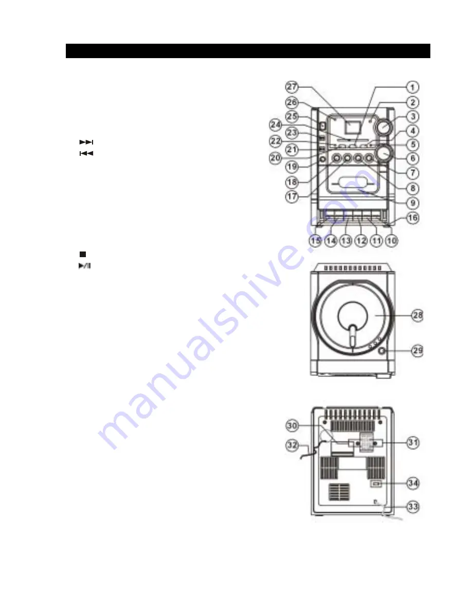
FEATURES AND CONTROLS 


1. PROGRAM Button 
2. Remote Sensor 
3. VOLUME Control 
4. REPEAT Button 
5. FM Stereo Indicator 
6. TUNING Knob 
7. 


SKIP+ Button 

8. 


SKIP- Button 

9. Cassette Door 

10. PAUSE Button 
11.  STOP / EJECT Button 
12. FAST FORWARD Button 
13. REWIND Button 
14. PLAY Button 
15. RECORD Button 
16. Cassette Button Door 
17. 


STOP Button 

18. 


CD PLAY / PAUSE Button 

19. HEADPHONE Jack 
20. BASSXPANDER Button 
21.  BAND Selector (AM / FM / FM ST.) 
22. BASSXPANDER Indicator 
23. FUNCTION Selector (TAPE / RADIO / CD) 
24. Dial Pointer 
25. POWER ON / OFF Button 
26. POWER Indicator 
27. LCD Display 
28. CD Door 
29. CD Door Open Button 
30. RIGHT Speaker Terminal 
31. LEFT Speaker Terminal 
32. FM Antenna Wire 
33. AC Cord 
34. VOLTAGE Selector (OPTIONAL) 


4

REMOTE CONTROL 

 
1. Infrared 

Transmitter 

2. RANDOM 

Button 

3. SKIP+ 

Button 

4. PROG. 

Button 

5. STOP 

Button 

6.  PLAY / PAUSE Button 
7. SKIP- 

Button 

8. REPEAT 

Button 

9. Battery 

Compartment 


INSTALLATION AND CONNECTIONS 


REPLACING Remote Control BATTERY 

1.  Turn over the remote control, and remove the battery door. 
2.  Install 1 “CR2025” lithium battery according to the polarity diagram on the battery compartment. 
3.  Close the battery door. 
 

BATTERY PRECAUTIONS 

Follow these precautions when using battery in this device: 
1.  Use only the size and type of battery specified. 
2.  Be sure to follow the correct polarity when installing the battery as 

indicated in the battery compartment. Reversed battery may cause 
damage to the device. 

3.  If the device is not to be used for a long period of time, remove the battery to prevent damage or 

injury from possible battery leakage. 

4.  Do not try to recharge battery, not intended to be recharged; they can overheat and rupture. 

(Follow battery manufacturer’s directions.) 


SPEAKER CONNECTION 

1.  Insert the speaker cables by pushing down the terminal lever of the Left 

  Speaker Terminal and the Right Speaker Terminal. 

2.  Connect the Left Speaker to Left Speaker Terminals, with white wire to the 

L+ and Black wire to the L-. 

3.  Connect the Right Speaker to Right Speaker Terminals, with white wire to 

the R+ and Black wire to the R-. 


MAIN CONNECTION 

This unit was designed to operate into an AC 

230 - 240V

 ~ 50Hz house current. 

Connecting this system to any other power supply could result in damage to the unit, which is not 
covered by your warranty. If this plug will not fit into your outlet, you should have your outlet 
changed by a qualified licensed electrician. 
1.  Unwind the AC Power Cord on the main unit. 
2.  Insert the plug into any convenient AC outlet. 


Summary of Contents for DC-AX20

Page 1: ...14 DC AX20 AU INSTRUCTION MANUAL MICRO STEREO SYSTEM ...

Page 2: ......

Page 3: ...COMPACT DISC PLAYER OPERATION 6 CASSETTE RECORDER OPERATION 8 MAINTENANCE 10 SPECIFICATION 12 To achieve the utmost in enjoyment and performance please read this manual carefully before attempting to operate the unit in order to became familiar with its features and assure you years of faithful trouble free performance and listening pleasure ...

Page 4: ...e any covers or attempt to gain access to the inside of the product Refer any servicing to qualified personnel Do not attempt to remove any screws or open the casing of the unit there are no user serviceable parts inside refer all servicing to qualified service personnel CAUTION TO REDUCE THE RISK OF ELECTRIC SHOCK DO NOT REMOVE COVER OR BACK NO USER SERVICEABLE PARTS INSIDE REFER SERVICING TO QUA...

Page 5: ...ton 14 PLAY Button 15 RECORD Button 16 Cassette Button Door 17 STOP Button 18 CD PLAY PAUSE Button 19 HEADPHONE Jack 20 BASSXPANDER Button 21 BAND Selector AM FM FM ST 22 BASSXPANDER Indicator 23 FUNCTION Selector TAPE RADIO CD 24 Dial Pointer 25 POWER ON OFF Button 26 POWER Indicator 27 LCD Display 28 CD Door 29 CD Door Open Button 30 RIGHT Speaker Terminal 31 LEFT Speaker Terminal 32 FM Antenna ...

Page 6: ...he battery to prevent damage or injury from possible battery leakage 4 Do not try to recharge battery not intended to be recharged they can overheat and rupture Follow battery manufacturer s directions SPEAKER CONNECTION 1 Insert the speaker cables by pushing down the terminal lever of the Left Speaker Terminal and the Right Speaker Terminal 2 Connect the Left Speaker to Left Speaker Terminals wit...

Page 7: ...lume to counter clockwise before you begin listening After you begin listening adjust the volume to a comfortable sound level Do not listen at extremely high volume level Extended high volume listening can lead to permanent hearing loss Once you set the volume do not increase it Overtime your ears adapt to the volume level so a volume level that does not cause discomfort might still damage your he...

Page 8: ... CD door Load a disc with label side upward with push down the CD door to close Playing Compact Disc 1 Switch ON the unit 2 Slide FUNCTION selector to CD position 3 Load a disc into the CD compartment and close the CD door After the CD Player read TOC then press CD PLAY PAUSE Button to start playback 4 Press STOP button to stop playback 5 Press down and release POWER ON OFF button to switch OFF un...

Page 9: ...sappear on the LCD Display Fig 3a Fig 3b PROGRAMMING CD The CD player enable program 20 tracks in a sequence of your choice 1 Press PROGRAM button in stop mode as below Fig 4a 2 Press and button to select the desired track to be programmed 3 Press PROGRAM button to entry memory 4 Continue to program repeat step 2 and 3 until memory full as below Fig 4c 5 Press PLAY PAUSE button on program mode to ...

Page 10: ...FUNCTION selector to TAPE position 3 Insert a pre recorded tape with exposed side downward and full spool to the left side 4 Press down PLAY button until locked to start playback 5 Press STOP EJECT button to stop playback 6 Press and release the POWER ON OFF button to switch OFF TAPE PLAY button START Press down until locked PAUSE button SUSPEND Press down until locked RESUME Press and release unt...

Page 11: ...ctor to CD position 2 Insert a blank tape with exposed side downward and full spool to the left side into cassette compartment and close cassette door 3 Press down z RECORD and PLAY button until locked first then press down PAUSE button until locked 4 Load a disc into CD compartment and close the CD door If necessary select a track by pressing and SKIP button 5 Press PLAY PAUSE button first to sta...

Page 12: ...been removed Recording on a cassette from which the tabs have been removed can be done by covering the tab openings with a piece of adhesive tape Care of Cassette Mechanism Gently clean the tape head and pinch wheel capstan assemblies after every 10 hours of use until all traces of oxide deposit have been removed A range of cassette care products is available The erase head and record play head an...

Page 13: ...bend the disc 3 Storage Store the disc in its case Do not expose discs to direct sunlight or high temperatures high humidity or dusty places Cleaning a disc Should the disc become soiled wipe off dust dirt and fingerprints with a soft cloth The disc should be cleaned from the center to the edge Never use benzene thinners record cleaner fluid or anti static spray Be sure to close the CD door so the...

Page 14: ...phone Impedance 16 32 ohm Speaker System Impedance 4 ohm 280Watts PMPO Driver 3 5 inch full range Cabinet Wooden Cloth Grille Detachable General Power Source AC 230 240V 50Hz DC 3V 1 pc of CR2025 lithium battery included or equivalent for remote handset Output Power 2 5 Watts RMS x 2 Power Consumption 23 Watts Dimension mm Main Unit 155 W 223 D 225 H Speaker Box 118 W 194 D 220 H approx ACCESSORIE...

Page 15: ......

Page 16: ...13 AU SANYO Electric Co Ltd Osaka Japan ...

Reviews: