


- 12 -
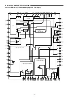
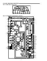
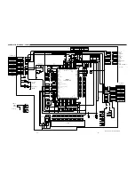
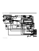
IC BLOCK DIAGRAM & DESCRIPTION
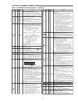
IC601 IC LC72338-9C41-E (Single-Chip PLL + Controller)
Pin name Pin No. I/O I/O Format
Functions
PA0
PA1
PA2
PA3
18
17
16
15
I
Pull-down
resistor
input
Port only for key return signal input.
The threshold voltage is set to a relatively low value.
When a key matrix is formed by combining PB and PC ports,
maximum three simultaneous key presses can be detected.
All of four pull-down resistor are set by the IOS instruction with
Pn=2, b1 and specification of resistor for each pin is impossible.
The input is disabled in clock stop mode.
PB0
PB1
PB2
PB3
PC0
PC1
PC2
PC3
14
13
12
11
10
9
8
7
O
Unbalance
CMOS
Push-pull
Port only for key source signal output.
Since the output transistor circuit is an unbalanced CMOS
structure, diodes to prevent short-circuiting due to multiple key
presses are not required.
In clock stop mode, these pins go to the output high-impedance
state and hold this state until an output instruction is executed.
PG0
PG1/SCK0
PG2/SO0
PG3/SI0
6
5
4
3
I/O
CMOS
posh-pull
General-purpose output/serial I/O ports. Schmidt type input
the IOS instruction performs switching between general-purpose
I/O ports and serial I/O ports, and between input and output for
general-purpose I/O ports.
• When used as general-purpose I/O ports these pins
can be set for input or output in bit units(bit I/O),
and are set for use as general-purpose I/O ports by
the IOS instruction with Pn=0.
b0=SI/O
0
0 • • • general-purpose port
1 • • • SI/O port
Specification of input or output is made by the IOS instruction
in bit units.
PG • • • Pn=6
0 • • • Input
1 • • • Output
• When used as serial I/O ports these pins are set for
serial I/O port use by the IOS instruction with Pn=0.
The content of serial I/O data buffer is saved or load by the
INR and OUTR instructions.
*Pin setup states when used as serial I/O ports
PG0 • • • general-purpose input or output
PG1 • • • SCK0 output in internal block
SCK0 input in external block
PG2 • • • SO0 output
PG3 • • • SI0 input
In clock stop mode, input is disabled and these pins go to
the high-impedance state.
During the power-on reset, these pins become general-purpose
input ports.
4.5MHz crystal oscillator pin.
XIN
XOUT
1
80
EO1
EO2
78
77
O
CMOS
tristate
-
I
O
Charge pump output pin.
These pins go to high-impedance state when the HOLD pin is set
low in the hold enable state.
In ckock stop mode, during the power-on reset and in the PLL
stop state, these pins go to the high-impedance state.
VSS
VDD
FMIN
AMIN
HCTR
76
31,73
74
75
70
72
-
I
I
I
I
-
Power supply pin.
FMVCO (local oscillator) input pin.
This pin is selected by the PLL instruction CW1 (b1=0,b0=don't
care). Capacitor coupling must be used for signalinput. Input is
disabled when the HOLD pin is set low inthe hold enable state.
Input is disable in clock stop mode,during the power-on reset,
and in the PLL stop state.
AMVCo (lcal oscillator) input pin.
This pin is selected and the band set by the PLL instruction
CW1 (b1,b0).
Capacitor coupling must be used for signal input.
Input is disabled when the HOLD pin is set low in the hold enable
state. Input is disabled in clock stop mode, during the power-on
reset, and in the PLL stop state.
b1 b0
Band
1
0
2 to 40MHz (SW)
1
1
0.5 to 10MHz (MW,NW)
Universal counter / general-purpose input port.
The IOS instruction b3 with Pn=3 switches the pin function
between universal counter input and general-purpose input.
• Frequency measurement
The universal counter function is selected by an IOS
instruction with Pn=3 and b2=0. HCTR frequency measure-
ment mode is set up by a UCS instruction with b3=0 and b2=0,
and counting is started with a UCC instruction after the count
time is selected. The CNTEND flag is set when the count
completes. To operate this circuit as an AC amplifier in this
mode, the input must be capacitor coupled.
• For use as the general-purpose input pin.
The general-porpose input port function is selected by an IOS
instruction with Pn=3 and b2=1. An internal register (address
OEH) input instruction INR(b0) is used to acquire data from
this pin.
Input is disabled in clock stop mede (the input pin will be pulled
down.) During the power-on reset, the universal counter function
is selected.
SNS
Voltage sense / general-purpose input pin port.
This circuit is designed for a relatively low input threshold voltage.
• For use as the voltage sense pin
This input pin is is used to determine whether or not a power
failure occurred after recovery from backup (clock stop) mode.
An internal sense F/F is used for this determination. The
sense F/F is tested with a TUL instruction (b2).
• For use as the general-purpose input port
When used as a genaral-purpose input port, the state is
sensed by using a TUL instruction (b3).
Since unlike other input ports, input is not disablle in clock
stop mode and during the power-on reset, special care is
required with respect to through currents.
Pin name Pin No. I/O I/O Format
Functions
LCTR
PH0/ADI0
PH1/ADI1
PH2/ADI2
PH3/ADI3
71
68
67
66
65
69
I
I
I
Universal counter (freqency and period measurement) / general-
purose input port.
This IOS instruction b3 with Pn=3 swithes the pin function
between universal counter input and general-puropse input.
• Frequency measurement
The universal counter function is selected by an IOS
instruction with Pn=3 and b3=0. LCTR frequency measure-
ment mode is set up by a UCS instruction with b3=0 and b2=1,
and counting is started with a UCC instruction after the count
time is selected. The CNTEND flag is set when the count
completes. To operate this circuit as an AC amplifier in this
mode, the input must be capacitor coupled.
• Period measurement
With the universal counter function selected, a UCS instruction
with b3=1 and b2=0 sets up the period measurement mode
and a UCC instruction starts counting after selecting the
count time. The CNTEND flag is set when the count
completes. In this mode, the signal must be input with DC
coupling to turn off the bias feedback resistor.
• For use as general-purpose input pin use.
The general-purpose input port function is selected by an IOS
instruction with Pn=3 and b3=1. An internal register (address
OEH) input instruction INR(b1) is used to acquire data from
this pin. Input is disabled in clock stop mode. (The input pin
will be pulled down.) During the power-on reset. The universal
counter function(in HCTR frequency measurement mode) is
selected.
HOLD
PLLcontrol and CLOCK STOP mode control pin.
Setting this pin low in the hold enable state disables input to the
FMIN and AMIN pins and sets the E0 pin to the high-impedance
state. To enter clocl stop mode, set the HOLDEN flag, set this pin
low, and execute a CKSTP instruction. To clear clock stop mode
set this pin high.
General-purpose input ports/ADC input pins.
The IOS instruction with Pn=7 switches the pin function between
genetal-purpose input ports and ADC inputs.
• For use as the general-purpose input port
The IOS instruction with Pn=7 specifies the use as general-
purpose input port in bit units.
• For use as ADC input pin
The IOS instruction with Pn=7 specifies the use as ADC in bit
units. The IOS instruction with Pn=1 specifies the pin to
convert. The UCC instruction (b2) starts a conversion.
The ADCE flag will be set when the conversion completes.
Note) Executing an input instruction for a port specified for ADI
use will always return low since input is disabled. These
pins must be set up for general-purpose input port usage
before an input instruction is excuted. (In other words, the
port must be set to the general-porpose input function
before the input instruction is executed.)
Input is disabled in clock stop mode. During the power-on reset
these pins go to the general-purpose input port function.
PJ0/DAC0
PJ1/DAC1
PJ2/DAC2
PJ3/DAC3
PK0/INT0
PK1/INT1
PK2
PK3
Vdd1
Vdd2
TEST1
TEST2
COM1
COM2
COM3
S1
|
S16
64
63
62
61
22
21
20
19
57
58
79
2
58
57
56
55
|
40
O
I/O
O
O
General-purpose output ports/DAC input pin.
The IOS instruction with Pn=9 switches the pin function between
general-purpose output ports and ADC inputs. Since these pins
are open drain circuit, pull-up resistors are required in exrernal
circuit accepting these outputs.
• For use as general-purpose output port
The IOS instruction with Pn=9F specifies general-purrpose
input port use in bit units.
• For use as DAC
The IOS instruction Pn=9 is used to switch the port in bit units.
DAC data is loaded into tne DAC (0 to 3) specified with the
DAC instruction, Although PWM waveform is output as soon
as the port is switched, the data prior to that load is output for
up to 114
µ
s (1/8.791kHz) after data is loaded.
The general-purpose output port function is selected after a power
-on reset, and the output go to the transistor off (H output) state.
General-purpose I/O / external interrupt ports
There is no instruction that switches the function between general-
purpose ports and external interrupt ports. These pins function for
input only when the external interrupt enable flag is set.
(Output disables)
• For use as general-purpose I/O port
These pins can be set for input or output in bit units (bit I/O).
The IOS instruction is used to specify input or output in bit
units.
• For use as external interrupt pin
This function can be used by setting the external interrupt
enable flags (INT0EN and INT1EN) in status register 2.
The corresponding pin is automatically set to the input port.
To enable interrupt operation, the interrupt enable flag (INTEN)
in status register 1 must also be set. The IOS instruction with
Pn=3, b1=INT1, and b0=INT0 is used to select rising or falling
edge detection.
In clock stop mode, input is disabled and these pins go to the high-
impedance state. During the power-on reset, these pins go to the
general-purpose input port function.
Nch
open drain
CMOS
push-pull
CMOS
three
value
output
CMOS
three
value
output
Pin for external application of 2/3 voltage of LCD drive bias.
Pin for external application of 1/3 voltage of LCD drive bias.
LSI test pin.
These pins must be either left open or connected to ground.
LCD driver common output pin.
Driver format 1/3 duty, 1/3 bias.
This pin is fixed at the low level in CLOCK STOP mode.
This pin is fixed at the low level after a power-on reset.
LCD driver common output pin.
Driver format 1/3 duty, 1/3 bias.
The frame frequency 100MHz.
This pin is fixed at the low level in CLOCK STOP mode.
This pin is fixed at the low level after a power-on reset.


