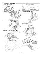
CDCHANGERREPLACEMENT
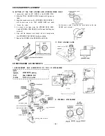
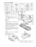
10. SETTING UP THE TRAY HOLDER AND UP/DOWN DRIVE GEAR
1. Loosen and install the SET SCREW of the SENSOR P.W.B.
2. Slide the TRAY HOLDER SLIDE forward until it goes no
further.
UP/DOWN DRIVE GEAR
3. Align the round mark on the UP/DOWN DRIVE GEAR 1
with the mark area on the TRAY HOLDER SLIDE, and install.
UP/DOWN CAM GEAR 2
4. Secure the screw.
l
Set the parts in such a way that the round marks on the two
5. As shown in the figure, place the UP/DOWN DRIVE GEAR
GEARS are horizontal.
2 and UP/DOWN CAM GEAR 2
a way that they are
horizontal.
6. Align with the triangular mark through the hole through which
the UP/DOWN CAM GEAR 2 teeth are visible.
7. Secure the SCREW of the SENSOR and GEAR.
11. TRAY HOLDER SLIDE
UP/DOWN MOTOR
(6142870440)
CD MECHANISM ADJUSTMENTS
1 .
REPLACEMENT AND LUBRICATION OF THE CD MECHANISM
I
MOLYKOTE,
I
I SG-7
SAN GREASE, SG-7
I
CONNECTOR
I
G-4748
OIL, G-4748
SPINDLE MOTOR
SLED RETARD GEAR 2
SLED MOTOR
RACK GEAR
MOTOR
LIMIT SW
BASE MECHANISM
S L E D
MARK
MARK
Summary of Contents for DC-F430AV
Page 16: ...EXPLODED VIEW CHASSIS I YOi 4 YO4 YOI d k 0 q f Y02 9 a L YO2 i y i A _ _ I ...
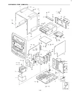
Page 17: ...EXPLODED VIEW CABINET U II G J I L Ei 16 ...
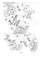
Page 29: ...EXPL ODED VIEW CD CHANGER MECHANISM PARTl 28 ...
Page 44: ... i I I ...
Page 51: ...1 I V P a CN421 C N 4 2 2 TO FRONT C N 4 2 4 TO AMP TO DECK 50 ...
Page 54: ...WIRING DIAGRAM CD ...
Page 56: ...WIRING DIAGRAM DECK 55 ...
Page 57: ... 56 ...
Page 58: ...WIRING DIAGRAM FRONT ...
Page 59: ...r e I 58 ...
Page 60: ...WIRING DIAGRAM POWER CENTER SURROUND SPEAKERS FRONT SPEAKERS SUB Ob OFE I 59 ...
Page 61: ...i I 60 ...
Page 62: ...WIRING DIAGRAM PRE AMP TUNER 61 ...
Page 63: ... 62 ...
Page 66: ...Apr 98 2300 NS Printed in Japan SANYO Electric Co Ltd Osaka Japan ...


