background image

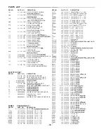
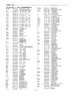
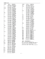
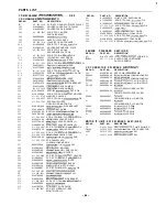
PARTS LIST

REF.NO.

L O O 0 1
LOO02
L G 4 9 3
P R 4 9 5
Q 4 4 0 0
or
or
or

or
or

or

or

or

or
or

o r
or
or
Q 4 4 3 6
or
or

or
or

or
or

o r
or
or
Q4471
o r
o r

o r
o r

or

PART NO.

DESCRIPTION

645 006 1417

 J

645 006 1417

  J

645 023 8987

FIXER

A

645 027 4169

405 011 8609

T R  

405 011 8500

T R  

405 015 6403

T R  

405 015 6205

T R  

405 011 8609

T R  

405 011 8500

T R  

405 015 6403

T R  

405 015 6205

T R  

405 011 8609

T R  

405 011 8500

T R  

405 015 6403

T R  

405 015 6205

T R  

405 016 3500

T R  

405 016 3302

T R  

405 016 3500

T R  

405 016 3302

T R  

405 016 3500

T R  

405 016 3302

T R  

405 

 3500

T R  

405 016 3302

T R  

405 141 3406

T R  

405 141 3505

T R  

405 005 2002

T R  

405 005 1906

T R  

405 011 8609

T R  

405 011 8500

T R  

405 015 6403

T R  

405 015 6205

T R  

405 011 8609

T R  

405 011 8500

T R  

405 015 6403

T R  

405 015 6205

T R  

405 011 8609

T R  

405 011 8500

T R  

405 015 6403

T R  

405 015 6205

T R  

405 011 8609

T R  

405 011 8500

T R  

405 015 6403

T R  

405 015 6205

T R  

405 141 3406

T R  

405 141 3505

T R  

405 005 2002

T R  

405 005 1906

T R  

405 141 3406

T R  

405 141 3505

T R  

405 005 2002

T R  

405 005 1906

T R  

405 033 6805

T R  

405 033 6706

T R  

405 033 6805

T R  

405 033 6706

T R  

405 011 8609

T R  

405 011 8500

T R  

405 015 6403

T R  

405 015 6205

T R  

405 033 6805

T R  

405 033 6706

T R  

405 033 6805

T R  

405 033 6706

T R  

405 033 6805

T R  

405 033 6706

T R  

405 033 6805

T R  

405 033 6706

T R  

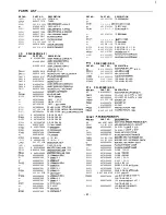
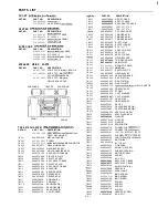
REF.NO.

Q 4 8 7 0

or
or

o r

or
or
or

or
o r

or

or

or

o r
o r

or
or
or

R4430

R4436
R4437
R4707
R4727
R4750

R4790
R 4 8 0 7

R4827
R4850

R4890
R4902
R4903
R4906
R 4 9 0 7
R4930
A4931
R4938
R4954
R4955
R4962
R Y 4 4 0
RY441
R Y 4 7 4

S A 4 9 3

T 4 9 0 0

PART NO.

DESCRIPTION

405 033 6805

T R  

405 033 6706

T R  

405 033 6805

T R  

405 033 6706 T R  

A 405 

001 9302 T R  

A 405 001 9302

T R  

405 141 3406

T R  

405 141 3505

T R  

405 005 2002

TR 

405 005 1906

T R  

A

405 095 1602

T R  

A

405 095 1701

T R  

A

405 138 6403

T R  

405 011 8609

T R  

405 011 8500

T R  

405 015 6403

T R  

405 015 6205

T R  

405 011 8609

T R  

405 011 8500

TR 

405 015 6403

T R  

405 015 6205

T R  

405 078 3005

TR 


405 000 6104

T R  

A 405 

001 9302 T R  

A 405 

001 9302 T R  

A

405 095 1602 T R  

A 405 095 

1701

T R  

A

405 136 6403

T R  

405 011 8609

T R  

405 011 8500 T R  
405 015 6403 T R  

405 015 6205

T R  

405 011 8609

T R  

405 011 8500

T R  

405 015 6403

T R  

405 015 6205

T R  

A

614 242 0126

RESISTOR 0.22 K- 3W

A

614 242 0126

RESISTOR 0.22 K- 3W

A

614 242 0126

RESISTOR 0.22 K- 3W

A

614 242 0126

RESISTOR 0.22 K- 3W

A

402 072 3505

RESISTOR 5.8 J- 

A

402 072 3505

RESISTOR 5.6 J- 1 W

A

402 079 5601

RESISTOR 0.22 J- 3W

A

402 078 8405

RESISTOR 330 J- 1 W

A

402 072 3505

RESISTOR 5.6 J- 1 W

A

402 072 3505

RESISTOR 5.6 J- 1 W

A

402 079 5601

RESISTOR 0.22 J- 3W

A

402 078 8405

RESISTOR 330 J- 

A

402 071 7207

FUSIBLE RES 100 JA 

A

402 071 7207

FUSIBLE RES 100 JA 

A

402 079 3607

FUSIBLE RES 220 JA 

A

402 079 3607

FUSIBLE RES 220 JA 

A

402 079 2808

FUSIBLE RES 22 JA 

A

402 071 0307

FUSIBLE RES 10 JA 

A

402 079 2709

FUSIBLE RES 0.47 JA 

A

402 071 1304

FUSIBLE RES 2.2 JA 

A

402 079 2808

FUSIBLE RES 22 JA 

A

402 079 2709

FUSIBLE RES 0.47 JA 

645 023 7171

RELAY

645 023 7164

RELAY

645 023 7164

RELAY

411 020 9902

SCR S-TPG BRZ+FLG 

411 021 6405

SCR S-TPG BIN 

614 239 1839

TERMINAL

614 239 1839

TERMINAL

1 9  

Summary of Contents for DC-F430AV

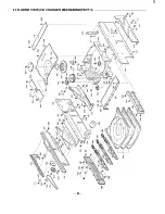
Page 1: ... 15 r _ _ I This service manual consists of DC F43OAVU Main unit 1 RB F43ORD Remote control and SX F430 FrontSpeaker I I I I system and SX CE43O Center Speaker system and SX LSR430 Surround Speaker system I l PRODUCT CODE No 129 530 06 UK 129 530 07 XE PARTS LIST 17 EXPLODED VIEW TAPE MECHANISM 26 EXPLODED VIEW CD CHANGER BASE MECHANISM 27 EXPLODED VIEW CD CHANGER MECHANISM 28 IC BLOCK DIAGRAM 81 ...

Page 2: ...0 Type 3 way bass reflex Drivers Woofer 13 cm cone type Midrange 5 cm cone type Tweeter piezoelectric Maximum power handling capacity 80 Watts peak Nominal impedance 6 ohms Dimensions W x H x D 210 x 330 x 240 mm Weight 3 6 kg CENTER SPEAKER SYSTEM SX CE430 Type Bass reflex Driver Full range 10 cm cone type Maximum power handling capacity 80 Watts peak Nominal impedance 8 ohms Dimensions W x H x D...

Page 3: ...STRALEN ÄR FARLIG DECKEL GEOFFNET UND WENN SICHERHEITSVERRIEGELUNG ÜBERBRÜCKT IST NICHT DEM STRAHL AUSSETZEN NÄKYMÄTTÖMÄLLE LASERSÄTEILYLLE ÄLÄ KATSO SÄTEESEEN I LUOKAN 1 LASERLAtTE KIASS 1 LLISERAPPARPT XE 4 REMOVAL INSTALLATION Press the POWER button and check that the STANDBY LED liohts Disconnect the power cord s plug from the electrical outlet 1 CABINET ASSEMBLY 1 Remove the 7 rear section mo...

Page 4: ... Remove the PRE AMPLIFIER P W board 3 Remove the 4 REAR SOCKET mounting screws 4 Remove the 2 HEAT SINK mounting screws 5 Remove the POWER P W board 7 TAPE MECHANISM BLOCK 1 Open the 2 CASSETTE LIDS O 2 Remove the 6 TAPE MECHANISM mounting screws 6 POWER TRANSFORMER 1 Remove the 4 POWER TRANSFORMER mounting screws 0 2 Remove the POWER TRANSFORMER 8 WIRING LAYOUT l Arrange the lead wires so that th...

Page 5: ...ection SG Set Adjustment Remark Circuit Input Output Frequency Position 1 Cover _ _ Connect Digital DC voltmeter to 87 5MHZ Low more than 0 8 V Voltage _ TPl l H TP12 E 108 0MHZ High less than 9 OV 2 Tracking Connect FM SG to FM Antenna Connect to VTVM 90 1 MHZ Low Max SG 8dB p V TPl3 L orTP14 R TPl5 E lOG lMHZ High SG Modulation 1 kHz 30 2 MW Step Adjusting Connection Circuit Input Output An Freq...

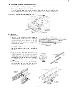
Page 6: ...BELT and PULLEY and the RACK GEAR which is intermeshed with the OPEN CLOSE IDLER GEAR moves forward during OPEN backwards during CLOSE l The HOME POSITION is reached when the largest square hole in the UP DOWN CAM GEAR is between the SENSORS 2 Rotate the UP DOWN CAM GEAR counter clockwise with OPEN CLOSE during PLAY or clockwise with normal OPEN CLOSE raise the GEAR BLOCK BRACKET stop at the selec...

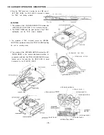
Page 7: ...d 3 The completion of TRAY movement causes the UP DOWN MOTOR to operate and lower the TRAY HOLDER putting the until to chucking status 4 The rotation of the UP DOWN MOTOR rotates the UP DOWN GEAR in the counter clockwise direction In connection with this the TRAY HOLDER SLIDE moves forward and at the same time the RIGHT SLIDE is moved backwards by the SYNCHRO LEVER TRAY SYNC LEVER TRAY H O L D E R...

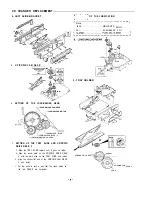
Page 8: ... TRAY GUIDE l Have the LEFT TRAY GUIDE HOLDER and TRAY GUIDE ready before proceeding 1 Turn the UP DOWN CAM GEAR and remove the setscrew of the TRAY HOLDER from the hole in the GEAR BLOCK BRACKET 2 Turn the UP DOWN CAM GEAR counter clockwise as far as it will go and remove the SCREWS 3 Remove the five setscrews of the LEFT TRAY GUIDEHOLDER and remove it in the direction of the arrow 4 When assembl...

Page 9: ...OAD IDLER 2 LLOADIUNLOAD D R I V E G E A R SETTING UP THE TRAY SLIDE AND UP DOWN DRIVE GEAR 2 1 Slide the TRAY SLIDE forward until it goes no further 2 Align the round mark on the UP DOWN DRIVE GEAR 2 with the mark area on the TRAY SLIDE and install 3 Align the shorter flat part of the UP DOWN CAM GEAR 2 and install l Set the parts in such a way that the round marks on the two GEARS are horizontal...

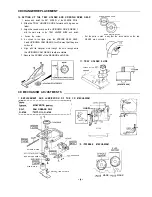
Page 10: ...n in the figure place the UP DOWN DRIVE GEAR GEARS are horizontal 2 and UP DOWN CAM GEAR 2 insuch a way that they are horizontal 6 Align with the triangular mark through the hole through which the UP DOWN CAM GEAR 2 teeth are visible 7 Secure the SCREW of the SENSOR and GEAR 11 TRAY HOLDER SLIDE UP DOWN MOTOR ASSY 10 5mm Liii I 6142870440 CD MECHANISM ADJUSTMENTS 1 REPLACEMENT AND LUBRICATION OF T...

Page 11: ...an them use a soft FT 7 5 O lmm 34 9 0 1 mm l cloth soaked in isopropyl alcohol 6 Apply a small amount of a mixture of the Three bond 2001 and 2015F bonding materials to the motor s shaft 7 Install the turntable as shown in the figure 8 Secure the turntable by pressing gently Be sure to wipe away by using a piece of cloth or similarmaterial any bonding material coming out of the hole TURNTABLE 2 R...

Page 12: ...S 614 296 0042 ASSY CONNECTOR S 614 265 0219 ASSY CONNECTOR S 614 296 0035 I CD PICK UP MAINTENANCE About pick up Optical lens Cleaning Clean the lens with the specified cleaning disc or moisten a cotton swab with isopropyl alcohol and cleaning paper Specified cleaning disc LC 1 Part code 645 026 1961 manufactured by SANYO Regarding procedure of cleaning with moisten cotton swab please refer to th...

Page 13: ...eously Within 1 second after pressing the MEMORY switch SERVICE MODE Tracking balance adjustment mode 5 Confirm that the oscilloscope waveform is symmetrical on the top and bottom in relation to OV VC 6 If it cannot be adjusted by fully rotating VRlOl cut the resistor R1108 1 Ok Q with a pair of pliersand adjust again 7 To cancel service mode disconnect the power cord s plug from the electrical ou...

Page 14: ...pe 4 All wiring should be returned to the original position after work is completed 2 Head azimuth l TAPE A 1 Load a test tape VTT 738 etc lOKHz for azimuth adjustment 2 Press the FORWARD PLAY button Normal playback 3 Use a flat tip screwdriver to turn the screw for normal azimuth adjustment so that the left and right outputs are maximized at the same phase during normal playback 4 Press the Tape ...

Page 15: ...he COMPUTER REC NORMAL button Service mode Normal speed TAPE TOP 0 SOUND PRESET 0 3 Adjust VR312 Tape A or VR314 Tape B so that the frequency counter show a reading of 3 OOOHz 4 Press the STOP button 5 To cancel service mode press the ON button 0 1 H I G H S P E E D TEST POINT 2 CHECKING THE MECHANISM TORQUES 1 Clean the head capstan and pinch roller before making any measurement 2 Check the both ...

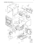
Page 16: ...EXPLODED VIEW CHASSIS I YOi 4 YO4 YOI d k 0 q f Y02 9 a L YO2 i y i A _ _ I ...

Page 17: ...EXPLODED VIEW CABINET U II G J I L Ei 16 ...

Page 18: ...CEMENT 49 5 0 51 5 2 5 3 5 4 5 5 5 6 5 7 5 8 5 9 6 0 61 6 2 6 3 6 4 PART NO DESCRIPTION 6 1 4 2 9 0 7 4 2 9 SPRING WIRE CASSEl l E L 6 1 4 2 9 0 7 4 3 6 SPRING WIRE CASSETTE R 6 1 4 2 9 0 7 0 7 8 KNOB ROTARY TUNING JOG 6 1 4 2 9 0 7061 KNOB ROTARY VOLUME JOG 6 1 4 291 8 3 0 2 ASSY DEC RING JOG 6 1 4 2 9 3 9 9 3 2 DEC PANEL FRONT L 6 1 4 2 9 6 9 8 9 2 DEC PANEL FRONT R 6 1 4 2 9 6 9 8 8 5 DEC WINDO...

Page 19: ... 2 04953 D 4 9 5 4 D 4 9 5 5 D 4 9 6 0 H S 4 9 0 H S 4 9 3 lC458 lC459 IC470 lC472 lC475 lC493 C 4 7 2 6 403 057 2407 POLYESTER 0 1 U J 50V o r 18 PART NO DESCRIPTION 4 0 3 0 5 7 2 4 0 7 POLYESTER 0 1 U J 50V 4 0 3 1 8 5 0 1 0 8 MT POLYEST 0 47U J 50V 4 0 3 0 6 7 7 8 0 5 MT COMPO 0 47U J 50V 4 0 3 0 5 7 2 4 0 7 POLYESTER 0 1 U J 50V 4 0 3 0 5 7 2 4 0 7 POLYESTER 0 1 U J 50V 4 0 3 0 5 7 2 4 0 7 POL...

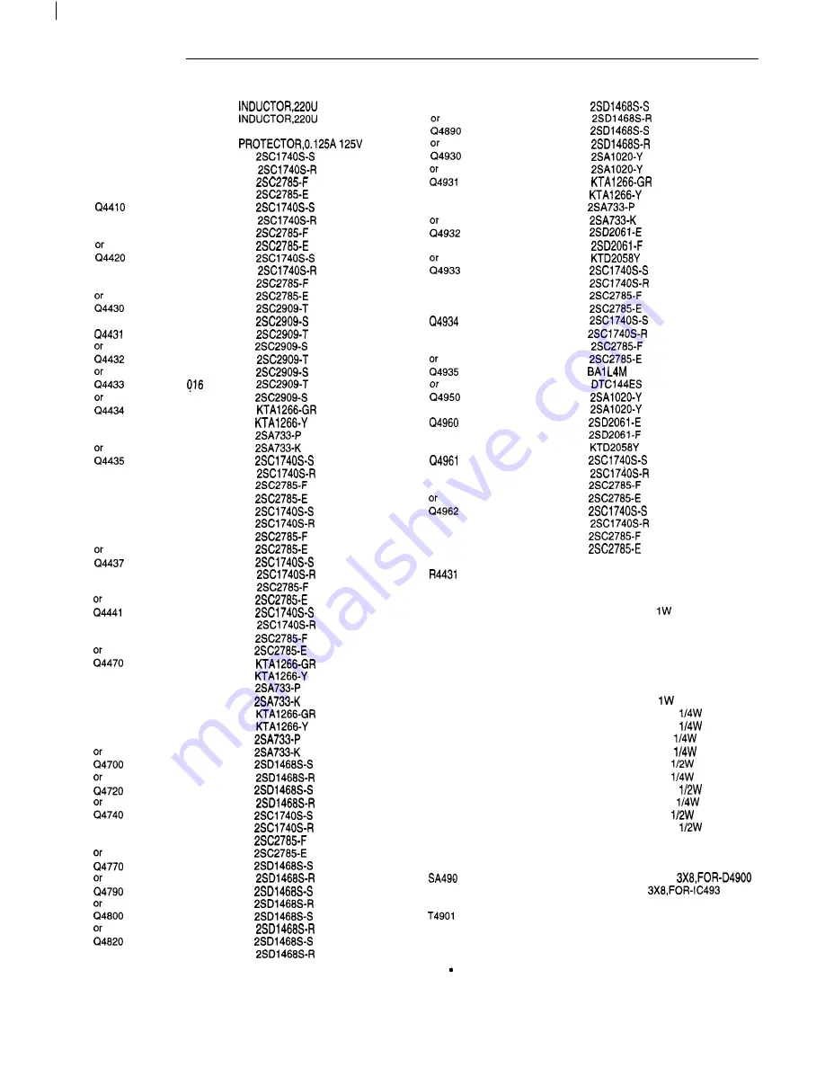
Page 20: ...SD1468S R REF NO Q4870 4890 t4930 ii4931 or or i4932 o r l4933 or or or cl4934 or o r z4935 t4950 or Cl4960 or or Q4961 o r o r t4962 or or or R4430 R4431 R4436 R4437 R4707 R4727 R4750 R4790 R4807 R4827 R4850 R4890 R4902 R4903 R4906 R4907 R4930 A4931 R4938 R4954 R4955 R4962 RY440 RY441 RY474 SA490 SA493 T4900 T4901 PART NO DESCRIPTION 405 033 6805 T R 2SDl468SS 405 033 6706 T R 2SDl468SR 405 033 6...

Page 21: ... MD IC LC72720N IC L A 2 7 8 6 IC LV1016 IC NJM4558M IC BA3842F IC BU209OF IC BU4052BCF IC NJM4558M TRANS RF TRANS RF TRANS OSC TRANS OSC INDUCTOR 1 M J INDUCTOR lOOU K INDUCTOR lOOU K INDUCTOR lOOU K INDUCTOR 47U K INDUCTOR 47U K INDUCTOR 47U K F I X E R REF NO PR401 Cl2140 o r o r or o r o r Q 2 1 5 2 Cl2153 Q 2 1 5 4 Cl2155 Q 2 1 5 6 Cl2157 Q 2 2 0 1 Q 2 3 1 0 o r or or or 2451 o r 2452 or 2453...

Page 22: ...09 4050087202 4050087301 4050003806 4051289001 4050370809 4050207402 REF NO PART NO DESCRIPTION or 4 0 5 0 2 0 7 2 0 4 TR 2SC945A K z1351 405 405 012 000 2002 0508 TR TR 2SC1815 GR DTA114ES o r 4 0 5 0 7 8 2 3 0 5 TR BNl A4M tl361 405 405 000 001 0508 1108 TR TR DTAll4ESRN2202 o r 4 0 5 0 7 8 2 3 0 5 TR BNlA4M 1371 405 405 001 000 0508 1108 TR TR RN2202 DTAll4ES or 4 0 5 0 7 8 2 3 0 5 TR BNlA4M or...

Page 23: ... or 4050782305 TRBNlA4M or 645 026 4771 SWlTCH ROTARY ENCODER VOL S6130 645 026 4764 SWlTCH ROTARY ENCODER TUNING o r 614 240 1002 SWITCH TACT o r 645 006 5958 SWITCH PUSH lP 1T S6131 614 220 5471 SWITCH TACT o r 614 240 1002 SWITCH TACT o r 645 006 5958 SWITCH PUSH lP 1T S 6 1 3 2 22 PART NO DESCRIPTION 6 1 4 2 2 0 5471 SWITCH TACT 6 1 4 2 4 0 1 0 0 2 SWITCH TACT 6 4 5 0 0 6 5 9 5 8 SWITCH PUSH 1...

Page 24: ...Sl33 4 0 7 0 0 7 9 9 0 4 DIODE GMAOl 4 0 7 0 1 2 4 4 0 6 DIODE 1 SS133 4 0 7 0 0 7 9 9 0 4 DIODE GMAOl 4 0 7 0 1 2 4 4 0 6 DIODE lSS133 4 0 7 0 0 7 9 9 0 4 DIODE GMAOl 4 0 7 0 1 2 4 4 0 6 DIODE lSS133 4 0 7 0 0 7 9 9 0 4 DIODE GMAOl 4 0 7 0 1 2 4 4 0 6 DIODE lSS133 4 0 7 0 0 7 9 9 0 4 DIODE GMAOl 4 0 7 0 1 2 4 4 0 6 DIODE lSS133 REF NO II3631 o r D 3 6 3 2 o r D3641 o r 0 3 6 4 2 o r HS301 IC351 I...

Page 25: ... T R DTCl44TS 405 105 7204 T R BAl L4Z 405 011 8609 T R 2SC174OS S 405 011 8500 T R 2SC1740SR 405 020 7402 T R 2SC945A P 405 020 7204 T R 2SC945A K 405 141 3307 T R KTC3198 GR 405 141 3208 T R KTC3198 Y 405 011 8609 T R 2SC174OS S 405 011 8500 T R 2SC1740SR 405 020 7402 T R 2SC945A P 405 020 7204 T R 2SC945A K 405 141 3307 T R KTC3198 GR 405 141 3208 T R KTC3198 Y 405 075 8409 T R DTC144TS 405 105...

Page 26: ... 0 5 0 T M 0 5 1 T M 0 5 2 T M 0 5 3 T M 0 5 4 T M 0 5 5 T M 0 5 6 T M 0 5 7 T M 0 5 8 T M 0 5 9 T M 0 6 0 T M 0 6 1 T M 0 6 2 T M 0 6 3 T M 0 6 4 T M 0 6 5 T M 0 6 6 T M 0 6 7 T M 0 6 6 T M 0 6 9 T M 0 7 0 T M 0 7 1 T M 0 7 2 T M 0 7 3 T M 0 7 4 T M 0 7 5 T M 0 7 6 T M 0 7 7 T M 0 7 8 T M 0 7 9 T M 0 8 0 TM081 TM082 T M 0 8 3 TM084 T M 0 8 5 T M 0 8 6 T M 0 8 7 TM088 T M 0 8 9 T M 0 9 0 T M 0 9 1...

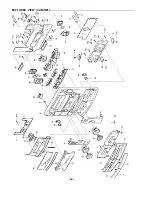
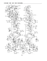
Page 27: ...EXPLODED VIEW TAPE DECK MECHANISM v TMo6 Mp54 d TMO67 0 TM079 TM006 TM007 TM059 TM062 T M I TMb90 TM013 TMPGi TM067 I I j fTMO6 T M 0 6 5 TM003 TM077 TM091 26 ...

Page 28: ... 2 9 SHAFT PICK UP RAIL o r 6 1 4 2 3 7 7 0 2 4 SHAFT PICK UP RAIL 7 0 4 6 1 4 2 3 7 7 0 9 3 GEARSLED RETARD GEAR 1 7 0 5 6 1 4 2 3 7 7 1 0 9 GEARSLED RETARD GEAR 2 7 0 6 6 1 4 2 3 7 7 1 1 6 GEAR SLED 7 0 7 4 1 2 0 4 7 3 9 0 4 SPECIAL SCREWSLED GEAR FIX 7 0 8 6 4 5 0 1 8 8 8 7 9 PICKUP LASER SF PlOOB o r 6 4 5 0 0 6 7 9 8 3 PICKUP LASER SF P100 7 0 9 6 4 5 0 0 9 9 9 6 0 FLEXIBLE FLAT CABLE PICK UP...

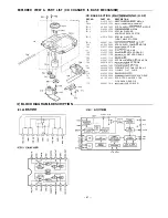
Page 29: ...EXPL ODED VIEW CD CHANGER MECHANISM PARTl 28 ...

Page 30: ...77312 5 2 0 6142661826 5 2 2 6450106491 5 2 5 6142661970 5 2 6 6142735992 5 2 7 614 270 2222 5 2 8 4120546202 5 3 1 4110228408 5 3 2 411 091 9702 5 3 3 411 028 2905 5 3 4 411 044 7007 5 3 5 6142661949 5 3 6 6142680476 5 3 7 4120546202 5 3 8 6450091186 5 3 9 411 098 8807 5 4 0 6142661994 541 6142779460 5 4 2 6142680469 551 411 098 8807 5 5 2 6142987032 5 5 3 411 098 8807 5 5 4 614 298 7025 5 5 5 64...

Page 31: ...2 7 8 0 7 SCR S TPG PAN 2X6 JOINT FIX 6 1 4 1 2 9 9 1 3 6 LUG UU SW LEAD DRESS 411 0 9 8 8 8 0 7 SCR S TPG BRZ FLG 3X6 LUG FIX 30 REF NO or 6 2 4 6 2 5 64C PARTS LIST 162 6 2 6 6 2 7 6 2 8 6 2 9 631 6 3 2 6 3 3 or 6 3 4 6 3 6 6 3 7 6 3 8 6 3 9 6 4 0 641 PART NO DESCRIPTION 411 0 9 8 8 8 0 7 SCR S TPG BRZ FLG 3X6 LUG FIX 6 1 4 2 8 7 0 4 4 0 ASSY MOTOR UP DOWN 411 0 9 8 8 8 0 7 SCR S TPG BRZ FLG 3X6...

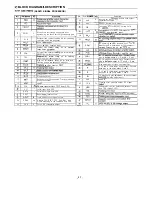
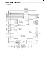
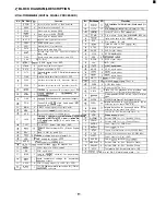
Page 32: ...ain High cut off frequency setting pin for focus and tracking phase compensation amplifier ITrackina amolifier neaative inout p Sled ampltfrer non Inverted Input 9 I TGU 1 I 1 36 1 PHD1 lo I TG2 I I pins to the photo diodes A C and B D pins I RF I V amolifier inverted inout Connect these pins to thebhoto diodes A i C and B D pins I Bias adjustment of focus error amplifier F I V and E I V amplifier...

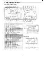
Page 33: ... IN B I Driver CH1 input for gain adjust V S S vDD I 3 Connect for base of external transistor g CH2 IN B 1 I IDriver CH2 input for gain adjust IO 1 CH2 IN A 1 I 1 Driver CH2 input 16 17 1 8 OP IN I Positive input of operational amplifier CH3 OUT A 0 Driver CH3 negative output CHS OUT B 0 Driver CH3 positive output 24 CHCIN B I Driver CH4 input for gain adjust 25 CHCIN A I Driver CH4 input D A T A...

Page 34: ...ROCESSOR EMPHI Digital Fi ter lbit DAC PCMD LRCK WDCK C2PO RFCK MINT0 MNTl MNT3 WFCK EMPH GFS XUGF GTOP I I I I D A _____ interfac digital CLV demodulato SQCK SQSO EXCK SBSO SCOR XLON SPOA CLOK XLAT DATA SENS XTSL 18 t Servo auto sequencer CLKO XLTO DATO to c 33 ...

Page 35: ...M signal input 37 BIAS I Inputs ccnstant current for asymmetry correction circuit XI ACVI r Inputs comparator voltage for asymmetry D A interface for 48 bit slot Ward clock f D A interface for 48 bit slot LR clock f FS lnouts LR clock to DAC 48 bit slot 4 4 PCMD 0 D A interface Serial data 2 SCOMP MBS first 45 PCMDI l Inputs audio data to DAC 48 bit slot 46 B C K 0 D A interface Bit clock 47 BCKI ...

Page 36: ...D lC422 462 NJM4558M lC475 NJM4558L VEE B INPUT ICI32 LB1641 L Pl O U T 1 IN1 GND VCCP OUT2 P2 53 Ei I vcc I N 2 input 1 Output 1Action IN1 IN2 1 OUT1 1 OUT2 1 1 0 0 Brake lC245 LC72131 MD IC131 LB1 648L OUTI OU 2 OU_T3 054 2 I N 3 IC231 LA1 832ML IN4 ...

Page 37: ...CH DC OUT C CH DC OUT L CH DC OUT R CH DC OUT V R E F L IN 6 3 _ I_ R OUT R IN S O U T 5 z 5 34 54 3 3 C OUT C M O D E C A P C TRIM DC CUT R BPFI L BPFl L BPF2 L BPF3 1 R BPF2 R BPF3 DC CUT DC CUT 1 R RECT 1 L RECT I DC CUT DC CUT L R RECT L R R E C T VLR TH VCS TH I LOG DIFF VLR 1 VLR 2 vcs 1 vcs 2 36 ...

Page 38: ... DIAGRAM DESCRIPTION IC421 LV1016 AGND L MIX OUT R MIX OUT VREF S OUT I is CLK DATA ENABLE B NR Vcc L IN R IN S IN DELAY OUT lC453 BA3842F BASS BOOST I 1 I L 1 I PRESET EQUALIZER 1468 7 50k IC461 605 BU4052BCF ...

Page 39: ...A KIA7805PI SOA CONTROL I I OUTPUT PASS TRANSISTOR OUTPUT IC604 BA3826S R I N 6 LIN 7 1 L 2 R 3 V E E 3 G N D 1 No 1Pin Name 1VO 1 Function I 16 1 Vm 1 IPowersupply SELECT 1 OUTPUT A 6pin I B 6pin I C 7pin 1 Vo 9pin L H L f 05 H L L f 06 L L L f 07 1 R E S E T 38 ...

Page 40: ...segment outout I I 2 7 EXSWB 0 Switch input B L 77 s4 0 L C D segment output 28 A M P C L K 0 IC clock control L 78 53 0 L C D segment output 29 EXSWA 0 Switch input A L 79 52 0 L C D segment output 30 VOL STB 0 Volume control signal outout al Sl 0 LCD segment output I 31 I DATA I 0 IDataoutout to tuner PLL ELE VOL I L I 81 I BREEL I I lDeckBreeloluseinout I I 1 A REEL I I IDeck A reel oluse inout...

Page 41: ...07 1 0 0 1 0 0 I 0 0 I 4 85 IC604 BA3826 04 Pin No 1 2 3 1 4 1 5 1 6 1 7 1 6 1 9 1 1 0 1 1 1 1 1 2 1 1 3 1 14 1 1 5 1 1 6 C D S T O P 0 0 5 07 0 85 1 0 85 1 3 8 1 3 6 1 3 6 1 0 0 1 0 0 1 5 67 1 0 0 1 0 0 1 0 0 1 7 35 1 0 0 1 0 0 Pin No 17 18 C D S T O P 0 0 5 07 IC605 BU4052BCF w PinNo 1 1 I 2 I 3 I 4 I 5 I 6 I 7 1 8 I 6 I 1 0 I 1 1 I 12 I 1 3 I 1 4 I 1 5 I 1 6 C D S T O P 1 0 0 1 0 0 1 0 0 1 4 85...

Page 42: ...I SCHEMATIC DIAGRAM CD r i I j i j I i j jI i i i i i i iI i p 1 3 IECHANISM 1 IX CHANGE CNI TPI 71 TP3 TP Remark All parts are changed without prior notice This is a basic schematic diagram 41 ...

Page 43: ... safety can be of special significance When replacing a component identified by A use only the replacement pans designated or Darts with the same ratinos of resistance wattage or voltage that are designated in the parts list in this manual Leakage current or resistance measurements must be made to determine that exposed parts are acceptably insulated from the supply circuit before returning the pr...

Page 44: ... i I I ...

Page 45: ...signated components in which safety can be of special significance When replacing a component identified by A use only the replacement parts designated or parts with the same ratings of resistance wattage or voltage that are designated in the parts list in this manual Leakage current or resistance measurements must be made to determine that exposed parts are acceptably insulated from the supply ci...

Page 46: ...I SCHEMATIC DIAGRAM FRONT TwmG 56001 56002 I I I I II I II d LAMP PWB Remark All parts are changed without prior notice This is a basic schematic diagram a ...

Page 47: ...an be of special significance When replacing a component identified by A use only the replacement pans designated or parts with the same ratings of resistance wattage or voltage that are designated in the parts list in this manual Leakage current or resistance measurements must be made to determine that exposed parts are acceptably insulated from the supply circuit before returning the product to ...

Page 48: ...SCHEMATIC DIAGRAM POWER t E a FRONT L R AMP IC470 STK407 050 FRONT CENTER CENTER SURROUND AMP IC472 STK407 050A Remark All parts are changed without prior notice This is a basic schematic diagram 47 ...

Page 49: ...y can be of special significance When replacing a component identified by A use only the replacement parts designated or parts with the same ratings of resistance wattage or voltage that are designated in the parts list in this manual Leakage current or resistance measurements must be made to determine that exposed parts are acceptably insulated from the supply circuit before returning the product...

Page 50: ... significance When replacing a component identified by A use only the replacement parts designated or parts with the same ratings of resistance wattage or voltage that are designated in the parts list in this manual Leakage current or resistance measurements must be made to determine that exposed parts are acceptably insulated from the supply circuit before returning the product to the customer Re...

Page 51: ...1 I V P a CN421 C N 4 2 2 TO FRONT C N 4 2 4 TO AMP TO DECK 50 ...

Page 52: ...SCHEMATIC DIAGRAM TUNER i I I _ _ _ _ _ _ __ Remark All parts are changed without prior notice This is a basic schematic diagram 51 ...

Page 53: ...n be of special significance When replacing a component identified by A use only the replacement parts designated or parts with the same ratings of resistance wattage or voltage that are designated in the parts list in this manual Leakage current or resistance measurements must be made to determine that exposed pans are acceptably insulated from the supply circuit before returning the product to t...

Page 54: ...WIRING DIAGRAM CD ...

Page 55: ...WIRING DIAGRAM LAMP PTl PT2 MOTOR LIMIT SW SENSOR CONNECTOR LAMP PTl MOTOR LIMIT SW SENSOR CONNECTOR ...

Page 56: ...WIRING DIAGRAM DECK 55 ...

Page 57: ... 56 ...

Page 58: ...WIRING DIAGRAM FRONT ...

Page 59: ...r e I 58 ...

Page 60: ...WIRING DIAGRAM POWER CENTER SURROUND SPEAKERS FRONT SPEAKERS SUB Ob OFE I 59 ...

Page 61: ...i I 60 ...

Page 62: ...WIRING DIAGRAM PRE AMP TUNER 61 ...

Page 63: ... 62 ...

Page 64: ...WIRING CONNECTION PRE AMPLIFIER P W 6 PTl P W B TAPE DECK MECHANISM mi SENSOR PCB SENSOR PCB 63 ...

Page 65: ...4 6 1 2 5 1 2 5 1 9 2 1 9 2 1 2 5 1 2 5 1 0 0 1 4 6 1 4 6 1 0 0 1 IC106 NJM4558D V Pin No 1 2 3 4 5 6 7 6 PLAY 3 8 3 2 3 2 0 0 3 2 3 2 3 8 8 8 S T O P 4 0 2 9 29 0 0 2 9 29 4 0 9 0 IC131 LB1648 Pin No I 1 I 2 I I UNLOAD 1 8 8 1 4 3 1 0 4 1 4 0 1 0 0 1 3 8 1 8 8 1 1 9 1 0 0 1 0 4 1 7 9 1 6 1 I I I 64 ...

Page 66: ...Apr 98 2300 NS Printed in Japan SANYO Electric Co Ltd Osaka Japan ...

Reviews: