CD CAHNGER OPERATION DESCRIPTION
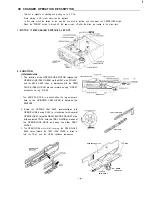
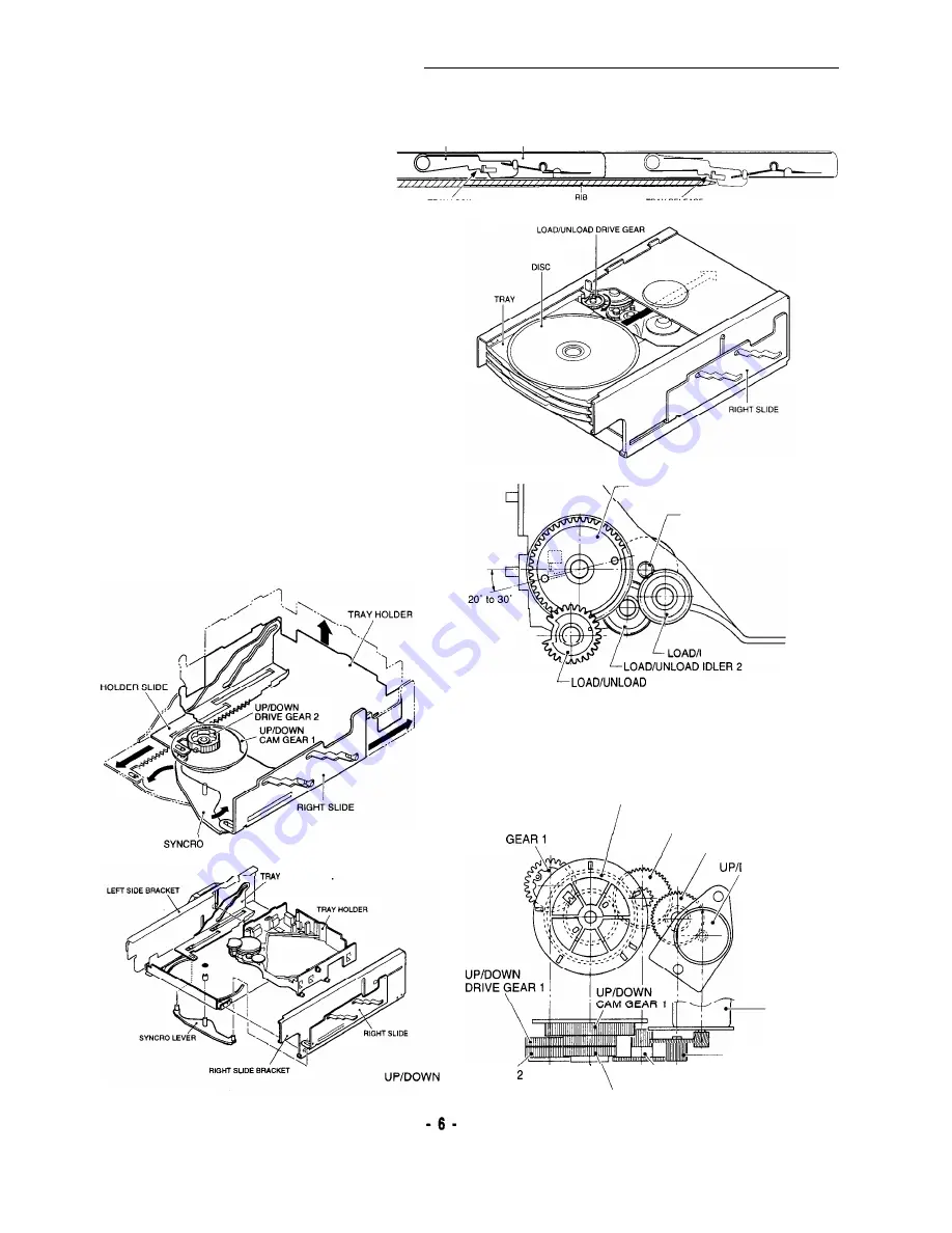
4. When the TRAY closes and it reaches the tip of RIB part of
LEFT TRAY GUIDE, the LOCK LEVER is lowered to release
the TRAY, and loading proceeds.
TRAY GUIDE HOLDER
LOCK LEVER
O
P
E
N
-
C
L
O
S
E
(2)LOADING
TRAY LOCK
TRAYRELEASE
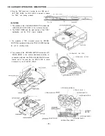
1. The rotation of the LOAD/UNLOAD MOTOR rotates the
LOAD/UNLOAD DRIVE GEAR in the clockwise direction.
2. The DRIVE GEAR and the gear portion of the TRAY
meshtogether and the TRAY movers backward.
3. The completion of TRAY movement causes the UP/DOWN
MOTOR to operate and lower the TRAY HOLDER putting
the until to chucking status.
4. The rotation of the UP/DOWN MOTOR rotates the UP/
DOWN GEAR in the counter-clockwise direction. In
connection with this, the TRAY HOLDER SLIDE moves
forward, and at the same time, the RIGHT SLIDE is moved
backwards by the SYNCHRO LEVER.
TRAY
LEVER
H O L D E R S L I
D
E
LOAD/UNLOAD CAM GEAR
LOAD/UNLOAD MOTOR
UNLOAD IDLER 1
DRIVE GEAR
UP/DOWN CAM GEAR 1
U/P/DOWN IDLER 2
UP/DOWN DRIVE
UP/DOWN IDLER 1
DOWN MOTOR
UP/DOWN
MOTOR
UP/DOWN IDLER 1
DRIVE GEAR
\
UP/DOWN IDLER 2
UP/DOWN CAM GEAR 2
Summary of Contents for DC-F430AV
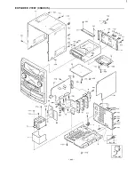
Page 16: ...EXPLODED VIEW CHASSIS I YOi 4 YO4 YOI d k 0 q f Y02 9 a L YO2 i y i A _ _ I ...
Page 17: ...EXPLODED VIEW CABINET U II G J I L Ei 16 ...
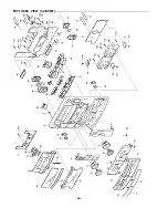
Page 29: ...EXPL ODED VIEW CD CHANGER MECHANISM PARTl 28 ...
Page 44: ... i I I ...
Page 51: ...1 I V P a CN421 C N 4 2 2 TO FRONT C N 4 2 4 TO AMP TO DECK 50 ...
Page 54: ...WIRING DIAGRAM CD ...
Page 56: ...WIRING DIAGRAM DECK 55 ...
Page 57: ... 56 ...
Page 58: ...WIRING DIAGRAM FRONT ...
Page 59: ...r e I 58 ...
Page 60: ...WIRING DIAGRAM POWER CENTER SURROUND SPEAKERS FRONT SPEAKERS SUB Ob OFE I 59 ...
Page 61: ...i I 60 ...
Page 62: ...WIRING DIAGRAM PRE AMP TUNER 61 ...
Page 63: ... 62 ...
Page 66: ...Apr 98 2300 NS Printed in Japan SANYO Electric Co Ltd Osaka Japan ...


