– 35 –
SCHEMATIC NOTES
SERVICE NOTES:
1. When replacing parts on circuit boards, clamp the lead wires to terminals before soldering.
2. When replacing high wattage resistors on circuit board, keep the resistor body 10 mm (3/8) from circuit board.
3. Keep wires away from high voltage and high temperature components.
PRODUCT SAFETY NOTICE
THE COMPONENTS DESIGNATED BY A
ON THIS SCHEMATIC DIAGRAM DESIGNATE COMPONENTS WHOSE
VALUES ARE OF SPECIAL SIGNIFICANCE TO PRODUCT SAFETY. SHOULD ANY COMPONENT
DESIGNATED BY A
NEED TO BE REPLACED, USE ONLY THE PART DESIGNATED IN THE PARTS LIST. DO NOT
DEVIATE FROM THE RESISTANCE, WATTAGE AND VOLTAGE RATINGS SHOWN.
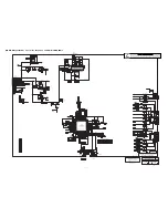
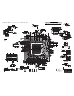
NOTES ON SCHEMATIC DIAGRAMS
1. All resistance values in ohms K=1,000 M=1,000,000.
2. Resistors specified with resistance value are “1/6DJ.”
3. Resistors specified with type of resistor, tolerence and resistance value are “1/4.”
4. Unless otherwise noted on schematic, all capacitor values less than 1 are expressed in μF (Micro Farad),
and the values more than 1 are in pF.
5. All capacitors are 50 WV rating unless oterhwise noted.
6. Unless otherwise noted on schematic, voltage reading taken with VOM from point indicated to chassis
ground. Voltage reading taken using color-bar signal VHF channel 5, all controls at normal. Line voltage at 120
volts. Some voltages may vary with signal strength.
7. Waveforms were taken with color-bar signal and controls set for normal picture. Waveforms marked with
an
8
may vary with signal strength.
8. The Symbol indicates a fusible resistor, which protects the circuit from possible short circuits.
9. Parts enclosed with are related with X-radiation.
10. Isolation border line. Cold Side Hot Side
11. Schematic part location numbers may not always match the schematic symbols.
The schematic symbols and part descriptions are correct and should be used.
The part descriptions will be listed under the location number in the parts list.
ELECTROSTATICALLY SENSITIVE DEVICES
Many solid-state devices (especially Integrated Circuits) are Electrostatically Sensitive, and, there-
fore, require special handling techniques as described under “Servicing Electrostatically Sensitive
Devices,” on page two in this service literature.
Summary of Contents for DP32649 - 32" LCD TV
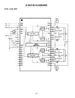
Page 23: ... 23 IC BLOCK DIAGRAMS IC001 Audio AMP ...
Page 24: ... 24 IC1670 Voltage Regulator IC803 EEPROM IC BLOCK DIAGRAMS CONT ...
Page 25: ... 25 IC1680 DC to DC Regulator IC1600 DC to DC Converter ...
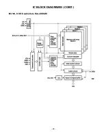
Page 26: ... 26 IC5500 Video Processing IC BLOCK DIAGRAMS CONT ...
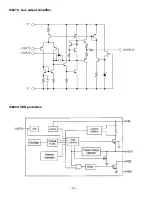
Page 27: ... 27 IC6600 USB protection IC6270 Low output Amplifier ...
Page 28: ... 28 IC5700 DDR Double Data Rate SDRAM IC BLOCK DIAGRAMS CONT ...

