background image

— 23 —

1AA4B10N1650A

PWB,MAIN-J3TZ

K1001

C002

K1021

C005

C008

C009

C012

C015

C017

C018

C019

C020

K_DEBUG

X801

C813

K1061

1

KSP

X2801

C251

C833

C834

C260

X251

C841

10

1

K8A

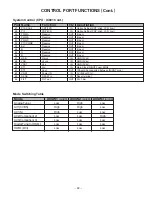
1

11

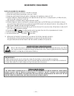
K8B

C851

1

13

IC001

K_DL

IC001A

E

IC803

C1002

C1003

C1004

C1005

C1201

C1203

K_IIC

C1021

C1022

C1023

C1025

C1602

C1026

C1603

C1027

C1605

C1606

C1607

K1101

C1612

C1613

C1614

C1617

C1618

C1810

C106

C107

C1061

C1062

C1063

C1065

C1066

C1067

KFAN1

KFAN2

C2806

C2808

C2811

C2813

C3401

C3402

C3403

C3406

C3407

C3408

C3409

C3411

C3412

C3413

C3414

C3418

C3420

C3421

C3422

C3423

C3424

C3427

C3428

C1101

C1102

C3430

R3419

R3422

R3423

R3424

R3427

R3428

R1101

R1102

R1103

R1104

R1105

R1106

R1107

R800

R3431

R3432

R802

R803

R805

SC1001

SC1002

SC1003

R808

SC1004

R809

SC1005

SC1006

R810

JP251

R813

R817

R819

C011

R821

R822

C016

SC1021

SC1022

R827

SC1023

R828

SC1024

R829

SC1025

R251

R254

R255

R256

R832

R833

R259

SC1801

SC1802

SC1803

SC1804

L1601

SC1805

L1602

SC1806

SC1807

L1605

L1606

L1607

C803

C804

L1609

R841

C805

C806

C807

C808

C809

L1802

L1803

L1610

L1804

L1611

L1805

L1612

L1806

L1613

L1807

L1614

C810

L1808

L1615

C811

L1809

L1616

C812

L1617

L1618

C814

L1619

R853

L1810

L1811

L1812

R857

L1620

R858

L1815

R859

R860

C825

C826

C828

SC1061

SC1062

SC1063

SC1064

R869

SC1065

C252

C835

Q102

R873

R874

C842

R882

C852

C853

R893

R896

R898

C1001

R101

R102

R103

R104

R105

Q1201

L1892

R106

Q1202

R109

L1896

R112

C1024

C1601

Q1021

D1002

Q1022

Q1023

C1604

R1001

R1002

R1003

C1608

R1004

R1005

R1006

R1007

R1008

R1009

Q1801

R1201

R1202

R1203

R1010

R1204

R1011

R1205

R1206

R900

R902

SC1101

SC1102

R907

C1620

C1621

C1623

C1624

C1625

R1021

C101

R1022

C102

R1023

C103

R1024

C104

R1025

C105

R1026

R1027

R1028

R1605

R1029

R1606

R1609

D1801

R1030

R1031

R1032

R1802

R1033

R1803

R1034

R1035

R1036

R1037

R1038

Q1251

Q1252

C1064

Q1061

Q1062

Q1063

R1040

R1810

R1811

R1042

R1813

R1044

R1814

R1045

R1046

R1819

R1626

R1251

R1252

R1253

R1061

R1255

R1062

R1256

R1063

R1064

R1258

R1065

R1259

R1066

R1067

R1068

R1069

R1260

Q2801

R1261

Q2802

R1262

R1263

R1070

R1071

R1072

R1073

R1267

R1074

R1268

R1075

R1269

R1076

R1077

R1078

C2815

R1080

R1082

R1084

R1085

R1086

L001

L002

R2801

R2804

R2811

R2814

R2815

R2816

R2817

R2818

R2819

C3410

+

C3417

+

C3419

Q251

C3425

Q252

C3426

R001

C3429

R002

R3403

R3404

R3405

Q1101

Q1102

R007

R016

D1003

C

D

E

B

C

D

E

6

5

4

3

2

1

MAIN BOARD FOIL SIDE

Summary of Contents for DP42746

Page 1: ...d Test Point Locations 22 24 Block Diagrams 25 28 Trouble Shooting Flow Charts 29 31 Control Port Functions 32 33 Schematic Notes 34 Pin Layouts 35 Capacitor and Resistor Codes 36 Board Connections 37 40 Schematic Diagrams 41 44 AS FILE NO SERVICE MANUAL Remote Control Plasma ColorTelevision DP42746 U S A CANADA ORIGINAL VERSION Chassis No 42746 00 NOTE Match the Chassis No on the unit s back cove...

Page 2: ...OTICE When replacing components in a receiver always keep in mind the necessary product safety precautions Pay special attention to the replacement of components marked with a star in the parts list and in the schematic diagrams To ensure safe product operation it is necessary to replace those components with the exact same PARTS SERVICING ELECTROSTATICALLY SENSATIVE DEVICES Semiconductors solid s...

Page 3: ...n Service Menu Use the Volume or key or number keys to adjust the data The or keys will increase or decrease the data sequentially The number keys 0 7 toggle only their respective bits between 1 and 0 and are used to change the Sub Address For example to change bit 5 press the number 5 key See below Note Using the or is not recommended due to possi ble rapid changes 3 Exit from the Service Menu Pr...

Page 4: ...xadeci mal 0A 00001010 binary See 087 above If this program code is wrong the TV will not operate properly Note 2 Option Data 2 NO 088 OP2 should be hexadeci mal 00 00000000 binary See 088 above If this program code is wrong the TV will not operate properly No TITLE INITIAL REFERENCE INITIAL SETUP INITIAL SETUP FUNCTION DATA HEX DATA HEX DATA BINARY 080 ATT 07 07 00000111 Attenuation MTS Input Lev...

Page 5: ... leakage 4KHz 300Hz TP317 R TP318 L Figure 2 Separation Adjustments SEPARATION ADJUSTMENT 7 Turn off the receiver and disconnect the AC power cord AC 120V line 8 Connect oscilloscope CH1 to TP317 and CH2 to TP318 and ground 9 Connect an MTS TV Stereo generator to antenna terminal 10 While pressing the VOLUME key reconnect the AC power cord The Service Menu will now appear 11 Select pilot 300Hz aud...

Page 6: ...gh LED Flashing When IC801 detects the Power Failure 3 times the LED will flash to indicate a power failure has occurred Note The LED does not flash for Temperature Failures Note If power failure is detected 3 times in 15 minutes the set will enter the standby mode and cannot be switched On To reset the operating programs of the CPU it is necessary to disconnect the AC cord for a short time Histor...

Page 7: ...o take the side cabinets off A 3X8 6pcs B 4X12 18pcs BACK CABINET REMOVAL CENTER Remove 31 screws to take the back cabinet off C 3X8 10pcs D 4X12 17pcs E 6X18 4pcs A B B B A B B A B B B B A B B B A B B A B B B B D E E D D D D E E D D D D D D D C C C C C C C C C D D C D D D ...

Page 8: ...ield case assembly parts off 3 FILTER BOARD REMOVAL Disconnect plug KAC Remove 3 screws 3X8 to take the filter board with the shield case assembly parts off 4 KEY SW BOARD REMOVAL Disconnect plug K8E Remove a screw 4X12 to take the key switch board with the panel button and holder assembly parts off 5 CONTROL BOARD REMOVAL The control board can be taken off after the filter glass is removed Refer ...

Page 9: ... padded or cushioned surface to protect the screen and finish Remove 2 screws 6X18 from each foot and remove FILTER GLASS REMOVAL 1 Remove the key switch board 2 Disconnect the following socket connections Control Board Main Board K8E Speakers Main Board KSP 3 Remove 8 screws 4X8 to take the panel module power unit and panel holders Mounting Brackets with boards off KAC K8E KSP K8P K8B K8A K8LV K8...

Page 10: ... assembly parts off 2 Remove the speakers 3 Remove a screw 4X10 to take the control board and holder off F F F F F F F F F F F F F F F F F F 4 Remove 20 screws G 3X8 to take the filter glass and upper plates off MECHANICAL DISASSEMBLY CONT G G G G G G G G G G G G G G G G G G G G FILTER GLASS REMOVAL Cont ...

Page 11: ...N8010 Filter Board Power Unit CN8001 Control Board Main Board K8E Speakers Main Board KSP PDP Module D TU Board K8LV 3 Remove the main board D TU board and filter board 4 Remove the 16 screws from the panel holders Mounting Brackets to take the panel module off H 4X8 14pcs I 5X10 2pcs H H H H H H H H H H H H H H I H H H H H I H Control Board Upper Holder Lower ...

Page 12: ...s of screws Using the correct screw is required to prevent damage The gasket is provided to prevent interference to other radio and television receivers The gasket must be returned to its previous position after servicing Lead wires must be redressed to previous posi tions after servicing MECHANICAL DISASSEMBLY CONT ...

Page 13: ...LID MT GLAZE WIRE WOUND CERAMIC RES FUSIBLE RES Performance Symbols A General B Non flammable Z Low noise Other Temperature coefficient Rated Wattage CARBON 4 7K J A 1 4W Read description of the Resistor as follows NOTES Example Carbon Metal Film Oxide Metal Film Composition Metal Glaze Wire Wound Ceramic Fusible RESISTORS NOTES Read description of the Capacitor as follows Example CERAMIC 100P K 5...

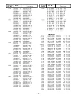
Page 14: ... 16V C1026 CEXLB1H2R2WAN ELECT 2 2U M 50V C1027 CEXLB1H2R2WAN ELECT 2 2U M 50V C1061 CEXLB1C101WAN ELECT 100U M 16V C1062 CEXLB1C100WAN ELECT 10U M 16V C1063 CEXLB1C100WAN ELECT 10U M 16V C1064 CK1E104ZLZFNG CERAMIC 0 1U Z 25V C1065 CEXLB1C100WAN ELECT 10U M 16V C1066 CEXLB1H2R2WAN ELECT 2 2U M 50V C1067 CEXLB1H2R2WAN ELECT 2 2U M 50V C1101 CEXLB1E4R7WAN ELECT 4 7U M 25V C1102 CEXLB1E4R7WAN ELECT ...

Page 15: ...0G INDUCTOR 220 OHM L805 1AV4L26B0130G INDUCTOR 600 OHM L806 1AV4L26B0130G INDUCTOR 600 OHM L1021 1AV4L2FB3R3MG INDUCTOR 3 3U M L1201 1AV4L2FB3R3MG INDUCTOR 3 3U M L1601 1AV4L26B2770G INDUCTOR 220 OHM L1602 1AV4L26B2770G INDUCTOR 220 OHM L1605 1AV4L26B0130G INDUCTOR 600 OHM L1609 1AV4L26B2770G INDUCTOR 220 OHM L1610 1AV4L26B2770G INDUCTOR 220 OHM L1611 1AV4L26B2770G INDUCTOR 220 OHM L1612 1AV4L26B...

Page 16: ...SA1179N M7P TR 2SA1179N M7 TB T2SA1235A1E P TR 2SA1235A1E T2SA1235A1F P TR 2SA1235A1F Q1022 T2SA1037AK RP TR 2SA1037AK T146 R T2SA1037AK SP TR 2SA1037AK T146 S T2SA1037K R P TR 2SA1037K T 96 R T2SA1037K S P TR 2SA1037K T 96 S T2SA1179 M6 P TR 2SA1179 M6 T2SA1179 M7 P TR 2SA1179 M7 TB T2SA1179N M6P TR 2SA1179N M6 TB T2SA1179N M7P TR 2SA1179N M7 TB T2SA1235A1E P TR 2SA1235A1E T2SA1235A1F P TR 2SA123...

Page 17: ...SC2412K T 96 R T2SC2412K S P TR 2SC2412K T 96 S T2SC2812 L6 P TR 2SC2812 L6 TB T2SC2812 L7 P TR 2SC2812 L7 TB T2SC2812N L6P TR 2SC2812N L6 TB T2SC2812N L7P TR 2SC2812N L7 TB T2SC3928A1R P TR 2SC3928A1R T2SC3928A1S P TR 2SC3928A1S Q3405 T2SC2412K R P TR 2SC2412K T 96 R T2SC2412K S P TR 2SC2412K T 96 S T2SC2812 L6 P TR 2SC2812 L6 TB T2SC2812 L7 P TR 2SC2812 L7 TB T2SC2812N L6P TR 2SC2812N L6 TB T2SC...

Page 18: ...1 10W R909 RGF1000JTCANL MT GLAZE 100 JA 1 10W R1001 RGF75R0JTCANL MT GLAZE 75 JA 1 10W R1002 RGF75R0JTCANL MT GLAZE 75 JA 1 10W R1003 RGF75R0JTCANL MT GLAZE 75 JA 1 10W R1004 RGF4703JTCANL MT GLAZE 470K JA 1 10W R1005 RGF4703JTCANL MT GLAZE 470K JA 1 10W R1006 RGF2200JTCANL MT GLAZE 220 JA 1 10W R1007 RGF2200JTCANL MT GLAZE 220 JA 1 10W R1008 RGF2200JTCANL MT GLAZE 220 JA 1 10W R1009 RGF2200JTCAN...

Page 19: ... GLAZE 0 000 ZA 1 10W R1819 RGE1000JTBANL MT GLAZE 100 JA 1 8W R3401 RGF1000JTCANL MT GLAZE 100 JA 1 10W R3402 RGF1000JTCANL MT GLAZE 100 JA 1 10W R3403 RGF1000JTCANL MT GLAZE 100 JA 1 10W R3404 RGF1000JTCANL MT GLAZE 100 JA 1 10W R3405 RGFR000ZTCANL MT GLAZE 0 000 ZA 1 10W R3406 RGF1004JTCANL MT GLAZE 1M JA 1 10W R3407 RGF1003JTCANL MT GLAZE 100K JA 1 10W R3416 RGF1501JTCANL MT GLAZE 1 5K JA 1 10...

Page 20: ...RBER MISCELLANEOUS A1901 1AA0B10N2020B ASSY PWB CONTROL J3TZ A1902 1AV4U20B24401 UNIT REMOCON RECEIVER KEY SWITCH PC BOARD CAPACITORS C1951 CK1E104ZLZFNG CERAMIC 0 1U Z 25V DIODES D1957 DZUDZS10B G ZENER DIODE UDZS10B TE 17 D1958 DZUDZS10B G ZENER DIODE UDZS10B TE 17 COILS L1955 1AV4L26B0130G INDUCTOR 600 OHM RESISTORS R1953 RGF1000JTCANL MT GLAZE 100 JA 1 10W R1954 RGF1000JTCANL MT GLAZE 100 JA 1...

Page 21: ... 10 1AA2DES0789 G DEC SHEET DTV 11 1AA2SDA0008 F STAND 2 12 1AA2DEM0371 DEC RC LED 13 1AA2DES0861 DEC SHEET DTV 14 1AV2BAAS015A BADGE SANYO 15 1AA2DES0712 F DEC SHEET VIZON 1AA6P1P5111 OWNERS MANUAL ENG SPA 1JC6P1P0218 OWNERS MANUAL FRENCH 1JC6P1P0230 QUICK N EASY SETUP SHEET 1AV0U10B43101 ASSY REMOCON 1AA2RCM0295 A RC BATTERY LID 1AV4W11B17100 CORD POWER 3 0MK CABINET PARTS LIST KEY NO PARTS NO D...

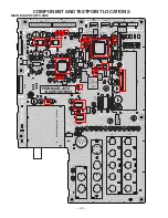
Page 22: ...7 R870 C258 R871 C259 Q101 R872 C836 C837 C838 R875 C839 R876 R877 R878 C840 C843 R883 R884 R885 L101 R886 L102 R887 L103 R888 L104 R889 L105 L106 L107 L108 1 5 K8E 1 4 K8F R890 R891 R892 R894 R895 R897 R899 C861 D801 C862 D802 D803 Q901 Q902 L2801 L2802 1 49 64 16 32 17 33 48 IC801 1 4 5 8 IC802 IC805 IC806 HD L1885 L1886 L1887 L1888 L1889 C1202 L1891 Q1203 L1893 R107 L1894 R108 L1895 L1897 L1898...

Page 23: ...L1807 L1614 C810 L1808 L1615 C811 L1809 L1616 C812 L1617 L1618 C814 L1619 R853 L1810 L1811 L1812 R857 L1620 R858 L1815 R859 R860 C825 C826 C828 SC1061 SC1062 SC1063 SC1064 R869 SC1065 C252 C835 Q102 R873 R874 C842 R882 C852 C853 R893 R896 R898 C1001 R101 R102 R103 R104 R105 Q1201 L1892 R106 Q1202 R109 L1896 R112 C1024 C1601 Q1021 D1002 Q1022 Q1023 C1604 R1001 R1002 R1003 C1608 R1004 R1005 R1006 R1...

Page 24: ...1660A F601 1PIN 1PIN PWB FILTER J3TZ K601 HOT COOL KAC COOL HOT 250V T10AH A30C5 C606 C608 LF601H2 LF601H4 LF601H3 LF601H1 VA602 VA601 C614 C613 LF602H2 LF602H1 LF602H3 LF602H4 K601H1 K601H4 K601H3 K601H2 F601B F601A LF601 LF602 C603 C609 K601 SCB061 SCB062 SCB063 SCB064 SCB066 SC601 SCB065 KAC KACH1 KACH2 C602 C607 C601 R601 X X X X X X X X HOT COOL PWB FILTER J3TZ B10N1660A COOL HOT A30C5 C606 C...

Page 25: ...ailure Normal H Failure L Normal L On H IC802 EEPROM Q803 804 Q801 Q901 902 8 44 62 IC803 RESET A1902 RC Pre AMP 2 IC806 3 IC805 3 3 P Fail D1606 D1607 7 IC001 Audio AMP 1 D1 8V 3 IC1604 2 A9V 4 IC1601 P Fail D1605 P Fail 1 A5V A9V D1601 P Fail 9 TU33V TU33V D1604 P Fail 3 A12V D1602 P Fail 3 4 D3 3V D1 8V D3 3V 12V_AMP IC1201 Video SW 16 12 19 IC1251 Audio SW A101 Tuner Analog IC3401 Audio Contro...

Page 26: ...PU IC801 Digital Module AV1_Y SW_Y CV 5 AV1_C 35 AV2_Y 23 AV2_Cb 21 AV1_L R L 14 R 5 AV2_L R L 15 R 2 AV3_L R L 11 R 4 TV_L R COMP 13 6 TV_CV 2 33 3 17 3 36 37 R 8 9 R OUT 39 AUDIO OUT_L 38 AUDIO OUT_R 13 4 2 3 4 L SEL_R SEL_L 33 34 DM_R DM_R DM_L DM_L AV2_Cr 25 IIC Bus UART UART IIC Bus IIC Bus R G B LVDS SPEAKER Right 12 11 L OUT SPEAKER Left AUDIO OUT Q101 Q1021 Q1022 Q1201 Q1023 AV3_Y 29 39 37...

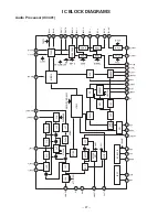
Page 27: ...STIN 26 VE 27 VEWQT 28 VETC 29 VEOUT 30 VCAIN 32 VCAWQT 31 VCATC 1 TOUT L 48 VOLIN L 4 LSOUT L 3 LSOUT R 7 DGND 6 SCL 5 SDA NOISE DET SAPIND IREF I2C BUS I F SW AMP 6dB LPF LPF HPF DeEm LOGIC SPECTRAL RMSDET RMSDET VE VCA 48 VOLIN R 44 TOUT R 41 TRE R 47 TRE L 45 BASS R 2 BASS L 40 SURRTC 38 TVOUT R 36 AUX2 R 37 AUX2 L 39 TVOUT L VOL L VOL L VOL R VOL R TREB TREB TREBLE BASS BASS BASS SURR M2 FEXT...

Page 28: ...d noise CH 1 AMP in REF AMP CH 2 AMP in CH 1 AMP out CH 2 AMP out TSD Protector Thermal protection curcuit Ripple Filter Block RNf1 Rf1 RNf2 Rf2 LOGIC LEVEL Control Input CONVERTER I O c O I I O c O I I O c O I I O c O I I O c O I I O c O I I O c O I I O c O I X COMMOM 13 0X 12 1X 14 2X 15 3X 11 0Y 1 1Y 5 2Y 2 3Y 4 Y COMMOM 3 VEE VSS VDD INH B A 7 8 16 10 9 6 IC1201 IC1251 Video and Audio Select ...

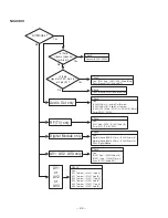
Page 29: ...ll 0V except 5V_ST line Is the voltage to all lines supplied Is the voltage to 5V_ST line supplied Is fuse F601 open Check Varistor VA611 Power Unit Check around CPU IC801 IC IC802 IC1803 Crystal X801 Transistor Q801 Power Unit Check Power Unit Diode D1605 Detected Voltage D5V D1606 D1607 D3 3V D1603 12V_AMP D1602 A9V D1601 A5V D1604 TU33V Power Failure Line CPU IC801 32pin Q803 Q804 ...

Page 30: ...1251 14pin L AV1 Terminal IC1251 5pin R AV2 Terminal IC1251 15pin L AV2 Terminal IC1251 2pin R AV3 Terminal IC1251 11pin L AV3 Terminal IC1251 4pin R Digital Module only Check Line Digital Module K6MA 37pin IC3401 33pin R Digital Module K6MA 39pin IC3401 34pin L Parts Digital Module AV1 AV2 AV3 only Check Line IC1251 3pin IC3401 36pin R IC1251 13pin IC3401 37pin L Parts IC1251 Audio SW Audio Out o...

Page 31: ...le K6MA 25pin Cr Parts Q1021 Q1022 Q1023 Digital Module AV2 only Check Parts Digital Module AV3 only Check Line Digital Module K5LV PDP Panel CN2077 Parts Around PDP Panel Digital Module Wire CN2077 K5LV To PDP Panel HDMI Digital Input only RF AV1 Check Line IC1201 3pin Q1201 Digital Module K6MA 33pin Parts Around IC1201 Video SW Check Line Q1061 Digital Module K6MA 29pin Y Q1062 Digital Module K6...

Page 32: ... 21 DBGP2 DBGP2 IN Terminal for De Bug 3 22 PC0 ENA DATA1 I O Writing on board ENA DATA1 23 PC1 DATA0 I O Writing on board DATA0 24 PC2 CLK IN Writing on board CLK 25 PC3 TB in IN Detection for Video Signal Time base H 26 PC4 Reserve OUT Open 27 P00 WDT out OUT Watch dog timer Reserved Open 28 P01 AV SW1 OUT Selection for AV Selector 1 29 P02 AV SW2 OUT Selection for AV Selector 2 30 P03 AV SW3 OU...

Page 33: ...gh FPD Low 48 P13 PDP LCD IN Option Setting PDP High LCD Low 49 PWMA Reserve OUT Open 50 PWMB Reserve OUT Open 51 PWMC Reserve OUT Open 52 P17 PWMD Reserve OUT Open 53 BL1 Reserve OUT Open 54 B Reserve OUT Open 55 G Reserve OUT Open 56 R Reserve OUT Open 57 HSB Hsync IN GND 0Vdc 58 VSB Vsync IN GND 0Vdc 59 VSS1 Vss IN GND 0Vdc 60 XT1 Xin IN Main Clock IN OUT Fosc 8MHz 61 XT2 Xout OUT Should be con...

Page 34: ...s more than 1 are in pF 5 All capacitors are 50 WV rating unless oterhwise noted 6 Unless otherwise noted on schematic voltage reading taken with VOM from point indicated to chassis ground Voltage reading taken using color bar signalVHF channel 5 all controls at normal Line voltage at 120 volts Some voltages may vary with signal strength 7 Waveforms were taken with color bar signal and controls se...

Page 35: ...E K CATHODE INTEGRATED CIRCUITS TRANSISTORS 1 DIODES PHOTO COUPLERS B BASE C COLLECTOR E EMITTER E CB E CB E C B E C B E CB E C B E C B E C B 3 2 1 3 2 1 GND 2 IN 1 OUT 3 1 1 TOP VIEW 1 CHIP TRANSISTORS B C E TOP VIEW B BASE C COLLECTOR E EMITTER CHIP RESISTORS TOP VIEW 123 12 x 10 12K ohm 3 IC DIODE ANDTRANSISTOR PIN LAYOUTS ...

Page 36: ...lypropylene T Tantalum K Ceramic H MT Composite P NP Electrolytic M MT Polypropylene RESISTOR Example 6 Y K 4 7 D 0 5 F 1 G 2 J 5 Value code K 10 Tolerance code M 20 Material code F Fusible Wattage rating N Metalized Carbon S Oxide Metalized Y Wire Wound C Solid D Carbon Film W Wire Wound April 2006 SMC Published in U S A For parts or service contact Sanyo Manfacturing Corporation P O Box 2000 333...

Page 37: ...EW HOLE 1 10GJ100C R1916 VCC VOUT GND GND GND U20B24401 A1902 1 2 3 4 5 1 10 GJ100C R1917 SC1902 1 2 6 3KK10GMB C1904 6 3KK10GMB C1903 KK1000LZB C1902 LED LED RC IN RC IN 5V_ST 5V_ST 1 10GZ0C R1900 SC1901 1 2 SCREW_14 SCA191 1 2 3 4 5 6 7 8 9 10 11 12 13 14 1 10GZ0 0 JP1910 SLP 381C51 D1903 K19E 1 5 SCREW_14 SCB191 1 2 3 4 5 6 7 8 9 10 11 12 13 14 Main Board Digital Module POWER UNIT PDP MODULE AS...

Page 38: ... SCRW3A SCREW_14 SCRW4B SCREW_14 SCRW3B SCREW_14 SCRW7B SCREW_14 SCRW8A SCREW_14 SCRW7A SCREW_14 SCRW6A SCREW_14 SCRW8B SCREW_14 SCRW5A SCREW_14 SCRW6B SCREW_14 SCRW5B 1 10GZ0C JP1851 1 10GJ100C R876 MA_GND D5V D3 3V 25KZ0 1LZF C1801 1 10GJ100C R1803 1 10GJ100C R1807 1 10GJ100C R1802 1 10GZ0C R1805 L26B0130G L1801 1 10GZ0C R1806 1 10GJ100C R1804 SC1801 1 10GJ100C R864 1 10GJ100C R865 1 10GJ 10KC R...

Reviews: