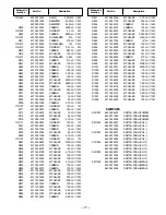
background image

— 20 —

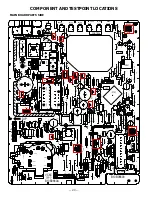
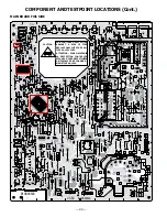
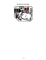
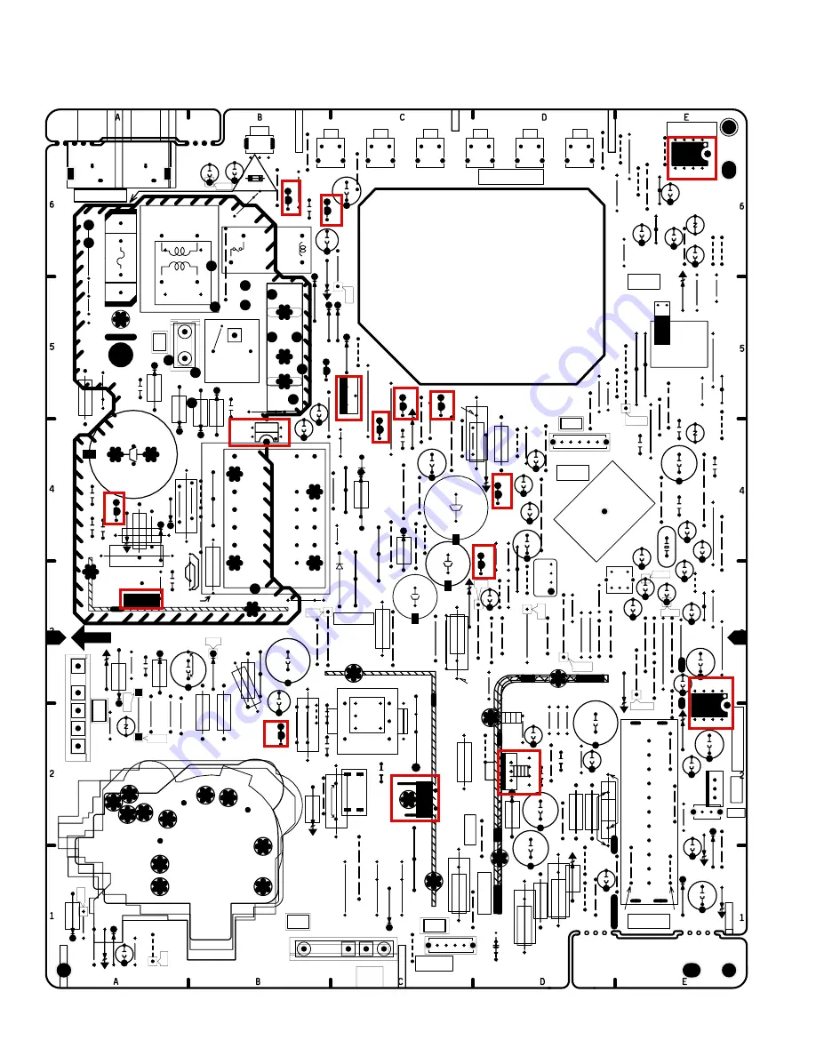
COMPONENT AND TESTPOINT LOCATIONS

B10B08800

8

5

4

1

VC8C

CONTROL

EEPROM

POWER

VOL-UP

VOL-DN

CH-UP

CH-DN

MENU

B10B0880A

IC801

E

DIP

26V

0.15~0.3A

KTP

GND

DATA

CLK

STA

TUS

ACK

KX

AUDIO OUT

????

4

1

1

3

E

TP7

TE7

1

5

IC101

TJ3

TJ5

TP50

TP51

TP113

TP132

TP11

TP16

1

4

POWER

TUNER

IVC

CPU

V-OUT

H-OUT

1

4

5

8

E

E

E

E

E

E

3

2

1

4A 125V

4A 125V

TJ2

KD

4

3

2

1

E

1

7

10

16

16

10

7

1

F601

TJ6

TP814

TJ1

1

2

TP10

E

C

B

1

7

IC802

D834

L821

X801

C891

C802

C822

C831

L801

C896

SW1903

SW1904

SW1902

SW1905

SW1901

SW1906

R865

R897

C131

C147

C272

C284

C509

C403

C253

C258

C211

C153

C212

X251

T151

C401

C252

C405

C505

KS

L146

X141

C151

R829

R823

R849

R272

R513

C1902

R517

R518

C421

R503

C106

R512

C501

C516

R509

R506

R504

R508

C503

C506

KT5P

KT4P

KT3P

KT2P

KT1P

C101

D101

C504

C502

R491

R494

R493

D487

R497

C481

D481

C493

R497A

D483

R481

R492

C487

C482

KB

R483

Q401

C511A

R511

KX1P

KX3P

KX4P

KX5P

R406

L402

C416

C417

T401

C511

R410

L404

C407

C406

C408

R106

A101

R411

C473

R353

R507

C411

D409

R408

D351

R857

R856

D801

C416A

C417A

D422

D421

R421

R482

C484

R428

R422

D482

D428

R423

D429

R498

T401A

R411A

R505

R837

Q490

D490

R490

C508

J401

J1901

J147

J504

J107

J501

J407

J412

J414

J406

J413

J408

J405

J502

J106

J802

L812

L811

J816

J813

J421

J801

J1902

J424

J281

J444

J282

J809

R142

A1901

L401

R408A

R511A

K1001

KSP

R001

C001

C008

IC001

J101

C011

J132

R401

R499

C497

C1001

R487

Q486

R486

C805

D680

R628

Q681

Q627

C693

Q693

R694

D693

Q695

R631

D624

C626

L623

D625A

L625

Q635

D627

D629

C683

IC681

C629

C631

C63

1A

C634

C628

R683

D486

IC601

J623

J621

J803

R402

J482

D802

R882

R881

R884

R883

T402H11C

C1002

D683

R686

C689

PS601

R601H2

R601A

PS601B

KD1P

KD2P

D604

R601H3

R601

R601H1

C606A

D603

D601

D602

C606

R602

A1

A2

F601B

F601A

LF601

LF601A

J608

C632A

C632

T601H14

T601H7

D612

C633

C633A

T601H2

T601H10

H

C609H2

C609H1

L602

R618

J601

R604

R612

C608A

R617

R611

Q613

C613

C614

C612

R613

D613

D614

C609

J102

J103

J814

J832

J831

J002

J108

T601A

RL601

T601

J481

J112

J111

C602

C604

J1903

J105

J114

J1904

J252

D408

C601

J116

D501

PS601

A

C256

J251

J001

J256

R400

J253

L256

C624

C625

C625A

C608

J804

J109

J110

J104

J506

J503

J418

J411

R004

R407

D653

R654

C627

D626

L626

C630

C004

R605

R603

R607

R615

J417

R488

R281

J811

J441

R499A

R486A

J271

R284

J143

R276

J624

R803

J416

J626

J486

R489

D502

R403

KSPA

R150

L846

J113

R496

D625

R407

A

R409

J690

R690

D001

R007

D617

C611

T402H11A

T402

Q402H1

Q402H2

Q402H3

Q402

T402H11

T402H7

T402H5

T402H4

T402H2

T402H1

T402A

T402H9

T402H10

T402B

T402H11B

Q601H2

Q601H1

Q601

IC501H1

IC501H2

IC501H3

IC501

MAIN BOARD PARTS SIDE

Summary of Contents for DS19330

Page 1: ...vice Literature is required You must refer to Notices to the Original Service Manual prior to servicing the unit G8MGM PRODUCT CODE 111372185 REFERENCE No SS780046 THIS CHASSIS IS SIMILAR TO MODEL DS19330 CHASSIS NUMBER 19330 02 SERVICE INFORMATION GIVEN IN THIS MANUAL IS ONLY THE DIFFERENCE INFORMATION FROM MODEL DS19330 CHASSIS NUMBER 19330 02 FOR ADDITIONAL SERVICE INFORMATION REFER TO THE SERV...

Page 2: ... 8995 CABINET BACK 610 311 6686 CABINET BACK 6 610 304 5245 BUTTON UNIT 610 312 4452 BUTTON UNIT 645 051 8485 RC TRANSMITTER 645 065 6934 RC TRANSMITTER 610 309 7107 OWNER S MANUAL ENG 610 312 7484 OWNER S MANUAL ENG 610 309 7114 OWNER S MANUAL SPA 610 312 7491 OWNER S MANUAL SPA 610 309 7121 OWNER S MANUAL FRE 610 312 7507 OWNER S MANUAL FRE MODEL DS19330 Chassis No 19330 02 MODEL DS19204 Chassis...

Page 3: ... JA 1 10W N A NOT USED R718 N A NOT USED 401 255 9006 MT GLAZE 82 JA 1 10W R724 401 255 9006 MT GLAZE 82 JA 1 10W N A NOT USED R728 N A NOT USED 401 255 9006 MT GLAZE 82 JA 1 10W T402 645 057 4832 TRANS FLYBACK 645 065 9386 TRANS FLYBACK A100 610 302 5476 ASSY PWB MAIN 610 312 3721 ASSY PWB MAIN 645 052 6077 TUNER U V 645 063 9814 TUNER U V A101 645 052 6091 TUNER U V 645 063 9821 TUNER U V A700 6...

Page 4: ...March 2004 2000 SMC Printed in U S A For parts or service contact 21605 Plummer Street Chatsworth CA 91311 U S A 300 Applewood Crescent Concord Ontario L4K 5C7 CANADA SANYO FISHER SERVICE ...

Page 5: ... Electrical Parts List 13 18 Cabinet Parts List 19 Component and Test Point Locations 20 23 Schematic Insert 25 32 Schematic Notes 25 Pin Layouts 25 Capacitor and Resistor Codes 25 Block Diagram 26 27 Voltage Charts 26 27 Waveforms 28 Schematic Diagrams 29 32 AS DS19330 Model COLORTELEVISION FILE NO Notice CORRECTION SERVICE FLASH PRODUCTION CHANGE ADD INFORMATION Please add this notice to the Ser...

Page 6: ...inet screw heads metal overlays control shafts etc Measure the AC voltage across the 1500 ohm resistor The AC voltage should not exceed 750 mV A reading exceeding 750 mV indicates that a dangerous potential exists The fault must be located and corrected Repeat the above test with the receiver power plug reversed NEVER RETURN A RECEIVER TO THE CUSTOMER WITHOUT TAKING THE NECESSARY CORRECTIVE ACTION...

Page 7: ...the AC power cord The Service Menu display will now appear 3 Select No 3C SCO Sub Color with or key Adjust the data with or key for 1D hex 4 Select No 3D STI Sub Tint with or key Adjust the data with or key for 08 hex 5 Select No 3F SSH Sub Sharpness with or key Adjust the data with or key for 05 hex 6 Select No 42 VS V Size with or key Adjust the data with or key for 45 hex 7 Select No 43 VSP7VPO...

Page 8: ... Red Drive 4B BGS5RGD4GD 08 0B 00001011 Blue Gamma Red Green Gamma Green Drive Reduction 4C BD 40 40 01000000 Blue Drive 4D SBI 20 40 01000000 Sub Bias 4E Not Used 4F Not Used 50 OSD 01 01 00000001 On Screen Display Contrast 51 BSD7CR6 40 40 01000000 Black Stretch Coring 52 Not Used 53 Not Used 54 FLS 01 01 00000001 Y C Filter Mode 55 GYA3CKO 02 02 00000010 G Y Angle Color Killer Operation 56 FBP6...

Page 9: ...ternately with 1 3 7 and 9 keys on the remote control See Figure 1 The Drive Level adjustment data will be written in the Service Menu No 4A RD and 4C BD automatically 1 2 3 4 5 6 7 9 8 RB RB BB BB N A GB N A GB N A FOR RED BIAS ADJUSTMENT FOR BLUE BIAS ADJUSTMENT FOR GREEN BIAS ADJUSTMENT Figure 1 Figure 2 1 2 3 4 5 6 7 9 8 RD RD BD BD N A N A N A N A N A FOR RED DRIVE ADJUSTMENT FOR BLUE DRIVE A...

Page 10: ...h add resistor R512 470 ohm 1W GRAYSCALE ADJUSTMENT 1 Set the picture controls to the Auto levels use MENU key and or key or RESET key 2 Turn off the receiver and disconnect the AC power cord 120V AC line 3 While pressing the MENU key reconnect the AC power cord The Service Menu display will now appear 4 Select NO 47 RB Red Bias NO 48 GB Green Bias and NO 49 BB Blue Bias with or key and set each d...

Page 11: ...ey 8 Adjust the data with or key for 820 mVDC 9 Press the MENU key to turn off the Service Menu display 10 Check brightness level on every active channel readjust repeat steps 5 9 if necessary Note Do not set to excessive brightness level otherwise the contrast level will be suppressed HIGH VOLTAGE HOLD DOWNTEST Every time the receiver is serviced the HIGH VOLTAGE HOLD DOWN circuit must be tested ...

Page 12: ...he MENU key to turn off the Service Menu display and disconnect oscilloscope from chassis SOUND ADJUSTMENT 1 Connect a color bar generator to the antenna terminals with audio signal of 1KHz at 100 modulation 2 Set the picture controls to the Auto levels 3 Connect oscilloscope lead to TP21 pin 75 of IC101 or C132 and lead to ground 4 Turn off the receiver and disconnect the AC power cord AC 120V li...

Page 13: ...f these failures remains uncorrected the CPU will shut off the power within three seconds Check the following if the unit is turned off by the power failure detector 1 Disconnect the AC power cord 120V AC line for at least 10 seconds 2 Connect a DC Voltmeter to the following TEST POINTS 3 Press the Power key and check for the proper voltage supplies 4 If any of these voltages is low the power fail...

Page 14: ...st Service Menu NO 47 RB Red Bias NO 48 GB Green Bias and NO 49 BB Blue Bias data each to 00 8 Select Service Menu NO 90 no vertical sweep 9 Adjust the Screen Control counterclockwise until the horizontal scan line is no longer visible 10 Select Service Menu NO 48 GB Green Bias and increase the data to produce a green raster If retrace lines appear reduce screen control slightly 11 Pull yoke back ...

Page 15: ...D GREEN Adjust six pole tabs angle to superimpose red blue and green vertical line Adjust six pole tabs together to superimpose red blue and green horizontal line RED GREEN BLUE RED GREEN BLUE Line movement when adjusting top of yoke in and out Figure 7 Side of Yoke Movement OUTER AREA CONVERGENCE ADJUSTMENT The outer area convergence is performed by positioning of the yoke as follows 1 Move the t...

Page 16: ...Care must be taken to keep these assemblies intact unless picture tube is being replaced Discharge the picture tube to the coating before handling the tube 1 Remove chassis referring to Chassis Removal instructions 2 Place cabinet s front face down on a soft surface 3 Remove the screw on each corner of the picture tube and GENTLY lift the picture tube out of the cabinet 4 Install a replacement pic...

Page 17: ...40 20 Y 150 10 Z 80 20 Rated Value P Pico Farad U Micro Farad Material CERAMIC Ceramic MT PAPER Metalized Paper POLYESTER Polyester MT POLYEST Metalized Polyester POLYPRO Polypropylene MT POLYPRO Metalized Polypropylene COMPO FILM Composite Film MT COMPO Metalized Composite STYRENE Styrene TA SOLID Tantalum Solid AL SOLID Aluminum Solid ELECT Electrolytic NP ELECT Non Polarized Electrolytic OS SOL...

Page 18: ...807 CERAMIC 1000P Z 2K C801 403 224 6108 CERAMIC 0 01U K 50V C802 404 084 3207 ELECT 47U M 16V C805 404 084 2200 ELECT 100U M 6 3V C807 403 234 9809 CERAMIC 18P J 50V C808 403 234 9809 CERAMIC 18P J 50V C822 404 084 2705 ELECT 10U M 16V C831 404 084 3801 ELECT 1U M 50V C834 403 224 6108 CERAMIC 0 01U K 50V C891 404 084 6901 NP ELECT 1U M 50V C892 403 224 5705 CERAMIC 1000P K 50V C894 403 323 3602 ...

Page 19: ...Q401 405 018 0507 TR 2SC3332 R 405 018 0606 TR 2SC3332 S Q402 406 017 1908 TR TT2140LS YB11 Q486 405 023 5009 TR 2SD400 E MP 405 023 5306 TR 2SD400 F MP Q490 405 023 5009 TR 2SD400 E MP 405 023 5306 TR 2SD400 F MP Q601 405 166 7601 TR 2SK2872 406 017 5500 TR 2SK2618LS CE11 Q613 405 016 9502 TR 2SC3069 Q627 405 009 6907 TR 2SB985 S 405 009 7003 TR 2SB985 T 405 089 0000 TR 2SA1707 S 405 089 0109 TR ...

Page 20: ... 4W R405 401 162 4101 MT GLAZE 5 6K JA 1 10W R407 401 059 6706 OXIDE MT 180 JA 1W R421 401 286 5305 MT FILM 2 4K FA 1 6W R422 401 052 6802 MT FILM 10K FA 1 6W R423 401 053 2605 MT FILM 3 3K FA 1 6W R428 401 024 9701 CARBON 12K JA 1 6W R441 401 150 6209 MT GLAZE 1K JA 1 10W R442 401 150 5905 MT GLAZE 10K JA 1 10W R443 401 150 5905 MT GLAZE 10K JA 1 10W R444 401 150 5905 MT GLAZE 10K JA 1 10W R449 4...

Page 21: ...BON 100 JA 1 6W R829 401 024 6700 CARBON 100 JA 1 6W R831 401 150 5905 MT GLAZE 10K JA 1 10W R832 401 150 5905 MT GLAZE 10K JA 1 10W R833 401 152 3206 MT GLAZE 330 JA 1 10W R834 401 150 5806 MT GLAZE 100K JA 1 10W R837 401 024 7400 CARBON 10K JA 1 6W R846 401 150 5905 MT GLAZE 10K JA 1 10W R847 401 256 7308 MT GLAZE 6 8K JA 1 10W R848 401 256 7308 MT GLAZE 6 8K JA 1 10W R849 401 027 5502 CARBON 6 ...

Page 22: ...CKET G8MAM A1901 645 041 1519 UNIT REMOCON RECEIVER 645 044 0519 UNIT REMOCON RECEIVER F601 423 007 1601 FUSE 125V 4A 423 007 1809 FUSE 125V 4A 423 018 8101 FUSE 125V 4A 423 029 8008 FUSE 125V 4A F601A 645 000 5077 HOLDER FUSE 645 016 0479 HOLDER FUSE F601B 645 000 5077 HOLDER FUSE 645 016 0479 HOLDER FUSE K701 645 028 0306 SOCKET CRT 8P K1001 645 040 5952 JACK RCA 2 PS601 408 046 5209 TH PTDAA1BF...

Page 23: ...101 SCREW 4X14 7 USED 6 610 304 5245 BUTTON UNIT 7 610 267 0851 CAP RC 8 610 285 5685 SANYO BADGE 610 304 6822 OWNER S MANUAL 645 051 8539 RC TRANSMITTER OR 645 051 8485 RC TRANSMITTER 610 290 1221 RC BATTERY COVER OR 610 290 1283 RC BATTERT COVER CABINET PARTS LIST KEY NO PARTS NO DESCRIPTION ACCESSORY PARTS LIST KEY NO PARTS NO DESCRIPTION 4 5 6 7 1 3 2 POWER MENU CH VOL AUDIO IN VIDEO IN 8 AS ...

Page 24: ...J408 J405 J502 J106 J802 L812 L811 J816 J813 J421 J801 J1902 J424 J281 J444 J282 J809 R142 A1901 L401 R408A R511A K1001 KSP R001 C001 C008 IC001 J101 C011 J132 R401 R499 C497 C1001 R487 Q486 R486 C805 D680 R628 Q681 Q627 C693 Q693 R694 D693 Q695 R631 D624 C626 L623 D625A L625 Q635 D627 D629 C683 IC681 C629 C 6 3 1 C6 31 A C634 C628 R683 D486 IC601 J623 J621 J803 R402 J482 D802 R882 R881 R884 R883 ...

Page 25: ...5V 4A 125V CAUTION MAIN BOARD COMPONENTS AND TEST POINTS GRID LOCATIONS PIC TUBE SOCKET BOARD COMPONENTS Part Loc Q701 N A Q711 N A Q721 N A Part Loc D429 A1 D612 B4 D802 E2 IC001 E2 IC101 D4 IC501 D2 IC601 C5 IC681 B6 IC801 E5 IC802 E6 Q401 B2 Q402 C2 Q486 D4 Q490 D3 Q601 A3 Q613 A4 Part Loc Q627 C5 Q681 B6 Q693 C5 Q695 C4 Q831 E6 R512 E2 R513 E2 TE7 A1 TP7 A1 TJ1 B3 TJ6 D3 TP16 E3 TP21 D3 TP50 A...

Page 26: ...01H3 R601 R601H1 C606A D603 D601 D602 C606 R602 A1 A2 F601B F601A LF601 LF601A J608 C632A C632 T601H14 T601H7 D612 C633 C633A T601H2 T601H10 H C609H2 C609H1 L602 R617 R618 J601 R604 R612 C608A Q613 D613 C613 C614 C612 R611 R613 D614 C609 J102 J103 J814 J832 J831 J002 J108 T601A RL601 T601 J481 J112 J111 C602 C604 J1903 J105 J114 J1904 J252 D408 C601 J116 D501 P S 6 0 1 A C256 J251 J001 J256 R400 J...

Page 27: ...E B10B0880B 1 5 4 1 SCREEN GND Q701 Q701A R706 K7B R717 R727 R707 R726 R707A R727A R717A K7U K7U1 C742 R716 K7S K701 R701 C702 Q721A Q721 Q711 Q711A R721 R711 R722 R723 K7Y1 K701A L701 PICTURETUBE SOCKET BOARD ...

Page 28: ... 24 June 2003 2000 SMC Printed in U S A For parts or service contact 21605 Plummer Street Chatsworth CA 91311 U S A 300 Applewood Crescent Concord Ontario L4K 5C7 CANADA SANYO Fisher Service Corporation ...

Page 29: ...1 20 0 IC801 21 0 IC801 22 0 4 IC801 23 4 9 IC801 24 4 9 IC801 25 4 9 IC801 26 GND IC801 27 GND IC801 28 4 9 IC801 29 GND IC801 30 GND IC801 31 GND IC801 32 GND POWER ON POWER OFF IC801 33 4 9 0 IC801 34 N C IC801 35 4 9 IC801 36 5 0 IC802 1 GND IC802 2 GND IC802 3 GND IC802 4 GND IC802 5 4 9 IC802 6 4 9 IC802 7 GND IC802 8 5 0 Device Pin Volts Mode POWER ON POWER OFF D612 1 26 1 9 7 POWER ON POWE...

Page 30: ...6 Q486 D486 R489 R604 C608 Q601 R613 R611 L602 R612 Q613 C614 R617 R618 D613 R616 C613 D614 R607 R603 C612 C609 C1002 C805 R1003 T601 TP814 TJ2 TJ1 TP113 TP132 TP11 TP12 TP21 TP20 TP16 TJ5 TP7 TE7 TP51 TP50 TP36 TP35 D408 R809 C693 C417 AT3 D626 L626 C627 J411 R488 R1901 R831 C831 Q831 R832 R833 D831 D653 R654 R605 R615 TJ3 IC101 R498 IC801 J608 J416 L404 C406 R407 R881 R882 R883 R884 L801 L821 KB...

Reviews: