background image

CIRCUIT DIAGRAM

2

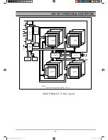
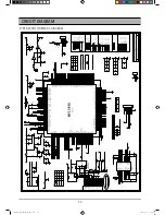
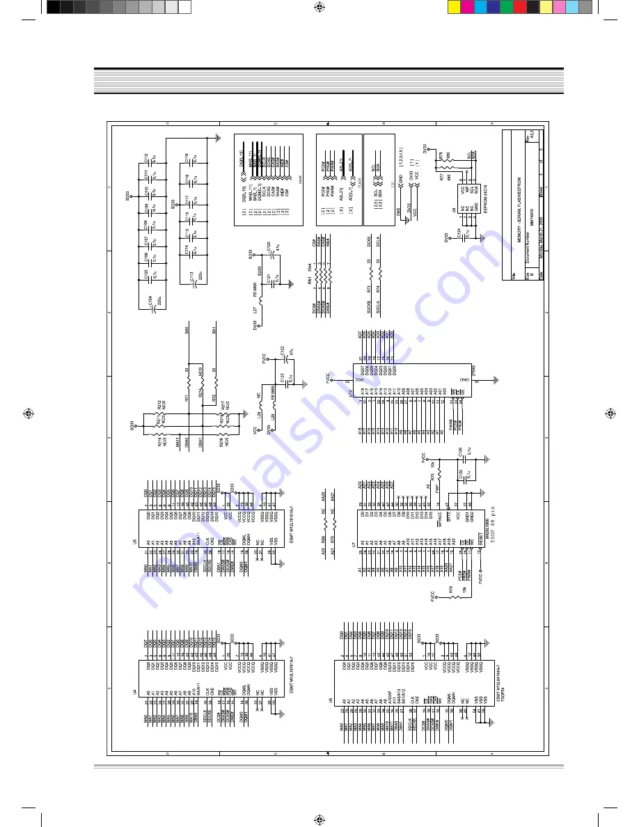
3) SDRAM & FLASH SCHEMATIC DIAGRAM

Sm(SANYO_DVD-DX500)051220.indd   21

2005-12-29   8:58:58

Summary of Contents for DVD-DX500

Page 1: ...FILE NO Specifications subject to change without notice SERVICE MANUAL REFERENCE No DVD DX500 DVD DX510 DVD Player ...

Page 2: ...FICATIONS 2 CIRCUIT OPERATIONAL DESCRIPTION 3 VOLTAGE CHARTS 17 CIRCUIT DIAGRAM 18 PCB CIRCUIT BOARD 27 WAVEFORMS 33 TROUBLE SHOOTING 38 INSTRUMENT DISASSEMBLY 44 PARTLIST 51 Sm SANYO_DVD DX500 051220 indd 1 2005 12 29 8 58 34 ...

Page 3: ...ticity Color 0 286 20 Load impedance 75Ω Component Y 1Vp p Pb Pr 0 7Vp p Load impedance 75Ω Power 100 240V 50Hz 60Hz 12W Dimensiones Body W x H x D 430 x 38 x 245 mm Packing 515 x 95 x 325 mm Weight Gross Net 2 9Kg 2 2Kg Notes Design and specifications in this instruction manual are subjected to change with out prior notice toimprove quality and function DVD Audio output standards Output Disc type...

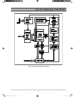
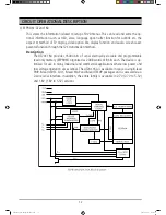
Page 4: ...ll be the STAND BY status which requires the least power for input the front panel key input the STAND BY ON key extinguished the LED Once the Power On key is entered u Com recognizes it and initiates each chipset performs sequential algorithms such as determining whether the disc is in or not and if in what type of disc is loaded Through this process it can read disc data before transmitting it t...

Page 5: ...ervo Mecha mounts with the optical pick up which allows reading the signal of a disc using laser beam and makes it operates and consists of the deck mechanism which allows loading a disc and reading the data Servo is a sort of circuit which allows operating the loader and recovering the data and consists of Motor Drive IC operating the spindle the sled the loading motor Loader Block Diagram Sm SAN...

Page 6: ... voltage through the internal OP AMP and drive on both sides and then the focus sig nal and the tracking signal will be output as VOFC VOFC and VOTK VOTK on actuator the sled signal and the spindle signal will be output as VOSL VOSL and VOLD VOLD on each motor For the load signal the input opening closing signal is output as VOTR VOTR through the loading PRE FWD REV circuit Motor Drive IC AT5888S ...

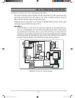
Page 7: ...ystem on chip SOC which incorporates advanced features like high quality TV encoder and state of art de interlace processing The MT1389 enables consumer electronics manufacturers to build high quality cost effec tive DVD players portable DVD players or any other home entertainment audio video devices Based on MediaTek s world leading DVD player SOC architecture the MT1389 is the 3rd generation of ...

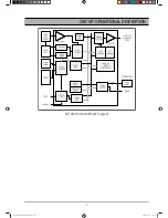
Page 8: ... CIRCUIT OPERATIONAL DESCRIPTION MT1389 Functional Block Diagram Sm SANYO_DVD DX500 051220 indd 7 2005 12 29 8 58 40 ...

Page 9: ... chip enable CE and outputenable OE controls MXIC s Flash memories augment EPROM functionalitywith in circuit electrical erasure and programming TheMX29F040 uses a command register to manage thisfunctional ity The command register allows for 100 TTL level control inputs and fixed power supply levels during erase and programming while maintaining maxi mum EPROM compatibility MXIC Flash technology r...

Page 10: ...STER MX29F040 FLASH ARRAY R E D O C E D X ADDRESS LATCH AND BUFFER Y PASS GATE R E D O C E D Y ARRAY SOURCE HV COMMAND DATA DECODER COMMAND DATA LATCH I O BUFFER PGM DATA HV PROGRAM DATA LATCH SENSE AMPLIFIER Q0 Q7 A0 A18 CE OE WE FLASH MX29F040QC 70 Block Diagram Sm SANYO_DVD DX500 051220 indd 9 2005 12 29 8 58 42 ...

Page 11: ...ircuit electri cal erasure and programming The MX26LV800T B uses a command register to manage this functionality The command register allows for 100 TTL level control inputs and fixed power supply levels during erase and programming while main taining maximum EPROM compatibility MXIC high speed Flash technology reliably stores memory contents even after 100 erase and program cycles The MXIC cell i...

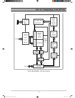
Page 12: ...11 CIRCUIT OPERATIONAL DESCRIPTION FLASH MX26LV800T B Block Diagram Sm SANYO_DVD DX500 051220 indd 11 2005 12 29 8 58 43 ...

Page 13: ...n The AT24C16A provides 16384 bits of serial electrically erasable and programmable read only memory EEPROM organized as 2048 words of 8 bits each The device is op timized for use in many industrial and commercial applications where low power and low voltage operation are essential The AT24C16A is available in space saving 8 lead PDIP 8 lead JEDEC SOIC 8 lead MAP and 8 lead TSSOP packages and is a...

Page 14: ...ata with MPEG decoder by 16 bit Description The M12L16161A is 16 777 216 bits synchronous high data rate Dynamic RAM orga nized as2 x 524 288 words by 16 bits fabricated withhigh performance CMOS technol ogy Synchronous design allows precise cycle control with theuse of system clock I O transactions are possibleon every clock cycle Range of operating frequencies program mable burst length and prog...

Page 15: ...s can run up to 143 MHz CL3 For handheld device applica tion we also provide a low power option the grade of 7L with Self Refresh Current under 400 A and work well at 2 7V during Self Refresh Mode For special application we provide extended temperature option the grade of 6I can work well in wide tem perature from 40 C to 85 C Accesses to the SDRAM are burst oriented Consecutive memory location in...

Page 16: ... 2 COLUMN DECODER SENSE AMPLIFIER CELL ARRAY BANK 0 COLUMN DECODER SENSE AMPLIFIER CELL ARRAY BANK 3 DATA CONTROL CIRCUIT DQ BUFFER COLUMN DECODER SENSE AMPLIFIER CELL ARRAY BANK 1 NOTE The cell array configuration is 4096 256 16 R E D O C E D W O R R E D O C E D W O R R E D O C E D W O R R E D O C E D W O R A0 A9 BS0 BS1 CS RAS CAS WE A11 SDROM PT480416TG 70 Block Diagram Sm SANYO_DVD DX500 05122...

Page 17: ...tial linearity no distortion mechanisms due to resistor matching errors no linearity drift over time and tempera ture and a high tolerance to clock jitter The CS4360 accepts data at audio sample rates from 4kHz to 200kHz consumes very little power and operates over a wide power supply range These features are ideal for cost sensitive multi channel audio systems including DVD players A V receivers ...

Page 18: ...GND S5V 3 3V D5V GND A5V GND 12V 12V J2 Pin number 1 2 3 4 5 6 Output voltage SW F F GND 24V STB5V Decode board input voltage CN1 Pin number 1 2 3 4 5 6 7 8 9 Output voltage GND S5V 3 3V D5V GND A5V GND 12V 12V VOLTAGE CHARTS Sm SANYO_DVD DX500 051220 indd 17 2005 12 29 8 58 48 ...

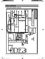
Page 19: ...18 CIRCUIT DIAGRAM 1 POWER SUPPLY SCHEMATIC DIAGRAM Sm SANYO_DVD DX500 051220 indd 18 2005 12 29 8 58 49 ...

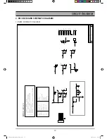
Page 20: ...CIRCUIT DIAGRAM 19 2 DECODE BOARD SCHEMATIC DIAGRAM 1 INDEX SCHEMATIC DIAGRAM Sm SANYO_DVD DX500 051220 indd 19 2005 12 29 8 58 51 ...

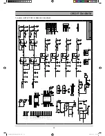
Page 21: ...CIRCUIT DIAGRAM 20 2 RF MPEG SCHEMATIC DIAGRAM Sm SANYO_DVD DX500 051220 indd 20 2005 12 29 8 58 54 ...

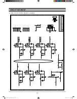
Page 22: ...CIRCUIT DIAGRAM 21 3 SDRAM FLASH SCHEMATIC DIAGRAM Sm SANYO_DVD DX500 051220 indd 21 2005 12 29 8 58 58 ...

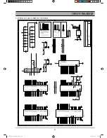
Page 23: ...CIRCUIT DIAGRAM 22 4 VIDEO OUTPUT PORT SCHEMATIC DIAGRAM Sm SANYO_DVD DX500 051220 indd 22 2005 12 29 8 59 01 ...

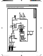
Page 24: ...CIRCUIT DIAGRAM 23 5 AUDIO OUTPUT PORT SCHEMATIC DIAGRAM Sm SANYO_DVD DX500 051220 indd 23 2005 12 29 8 59 04 ...

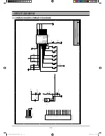
Page 25: ...CIRCUIT DIAGRAM 24 3 CONTROL BOARD SCHEMATIC DIAGRAM Sm SANYO_DVD DX500 051220 indd 24 2005 12 29 8 59 07 ...

Page 26: ... M 2 5 4 7 6 3 1 k 0 1 7 R 0 3 C V 6 1 F U 0 1 9 1 C P 0 0 1 K 3 3 5 2 R 1 R k 7 4 7 2 R K 0 0 1 K 0 1 9 1 R 5 1 C V 0 5 F U 3 3 9 2 C 3 0 1 1 2 1 C V 5 2 F U 2 2 3 2 C U 1 0 2 1 C 3 2 2 9 2 R K 0 1 2 2 2 7 C 3 1 C 3 2 2 1 L B F 0 2 6 8 R 2 L B F P 0 0 1 5 2 C 4 C K 4 0 1 1 N C P 4 S N C 1 2 3 4 1 Q 5 1 8 1 C S 2 1 2 3 B C E 8 1 C V 0 5 F U 7 4 K 0 0 1 4 2 R 1 3 R K 7 4 4 1 C 3 0 1 0 2 6 4 R 7 2 C...

Reviews: