background image

GB–1

CONTENTS

COMPACT DISC CARE ........................................................................................................................... 2

DIGITAL DISPLAY .................................................................................................................................... 3

DETACHABLE FRONT PANEL ................................................................................................................ 4

GENERAL OPERATION .......................................................................................................................... 5

ADJUSTING EQUALIZER AND SOUND STAGE .................................................................................... 7

RADIO OPERATION ................................................................................................................................ 9

CD OPERATION ..................................................................................................................................... 11

ERROR SIGNS ...................................................................................................................................... 12

HINTS FOR PROPER AND SAFE OPERATION .................................................................................. 13

TROUBLESHOOTING ........................................................................................................................... 14

ACCESSORIES AND HARDWARE ....................................................................................................... 15

INSTALLATION ....................................................................................................................................... 15

UNIT REMOVAL ..................................................................................................................................... 16

ELECTRICAL CONNECTIONS .............................................................................................................. 17

LINE OUT CONNECTIONS ................................................................................................................... 18

CAUTION

• This unit is designed to operate on 12 volts DC, NEGATIVE ground electrical systems only.
• When fuse replacement is necessary, use only a 10 amp fuse. Do not replace with a higher rated fuse. If

the fuse blows often, carefully check all electrical connections for any short circuits and have your car’s
voltage regulator checked also.

• Do not install the unit where it will be exposed to direct sunlight or hot air discharged from the car heater.
• Do not expose the unit to water or moisture.
• To avoid damaging the unit, never insert anything other than a compact disc into the disc slot.
• This unit should not be adjusted or repaired by anyone except qualified service personnel.

If servicing is required, return the unit to an authorized SANYO mobile audio dealer.

• Use the Controls or adjustments or performance of procedures other than those specified herein may

result in hazardous radiation exposure.

• Changes or modifications not expressly approved by SANYO may void the user’s authority to operate

this equipment.

 FXD-785GD_body

8/6/03, 10:05 PM

1

Summary of Contents for FXD-785GD

Page 1: ... 5 6 AUDIO MUTE VOL RPT SHF REL LOUD LO DX ATP TUN TUN TRK TRK POWER Full Panel Detachable High Power FM AM Stereo Receiver Compact Disc Player ISO Mounting with Removable Trim Ring English OPERATING INSTRUCTIONS GB 1 GB 18 FXD 785GD_Cover 8 6 03 10 07 PM 1 ...

Page 2: ...rical connections for any short circuits and have your car s voltage regulator checked also Do not install the unit where it will be exposed to direct sunlight or hot air discharged from the car heater Do not expose the unit to water or moisture To avoid damaging the unit never insert anything other than a compact disc into the disc slot This unit should not be adjusted or repaired by anyone excep...

Page 3: ...damage the plastic surface of the disc When not using the disc player for extended periods of time remove the compact disc and return it to the plastic storage case This will protect the disc from dust and exposure to the sun This unit has been designed to play compact discs bearing the identification logo shown on the left No other discs can be played Recommended CD R RW Media Data may not be pro...

Page 4: ...o Position Shuffle Play Repeat Play Scan AM Bands FM Bands Loudness CD Mode Disc IN Preset No Track No Mute Volume Audio Control Level Indicator FM Stereo Local DX BASS TREBLE Equalizer Disc IN indicator Radio Preset Chan nel Number Track Number Manual Tuning FXD 785GD_body 8 6 03 10 05 PM 3 ...

Page 5: ... than 10 seconds the mi crocomputer of the unit returns to the initial settings If the display window is not properly shown or the unit malfunctions press the eject button for more than 10 seconds Note The unit will not operate if it is installed incorrectly CAUTION Do not attempt to remove the panel in a manner other than that described above When installing the panel do not force it into the uni...

Page 6: ...icator on the display is blinking To restore the previous volume level press POWER MUTE button 1 again SETTING THE CLOCK 3 2 6 7 The clock uses a 24 hour display system 1 Press the DISP button 3 for more than 2 seconds 2 Press the following buttons to set the clock VOL dial 2 Adjust the hour and minutes TUN TRK 6 To activate Hour blink TUN TRK 6 To activate Minute blink BAND ATP 7 Adjust the minut...

Page 7: ...ECT 5 When listening to music at low volume levels this feature will boost the extremes of the bass and treble ranges to compensate for the negative characteristics of human hearing Press the LOUD LO DX button 5 The LOUD indicator appears in the display window Pressing the button again will cancel this feature LOCAL DISTANT LO DX SELECTION 5 This feature is used to select the strength of the signa...

Page 8: ...osition indicator blinks and adjusted sound stage is stored TO CALL THE SOUND STAGE 2 Press the appropriate Preset buttons 2 to call the desired sound stage during the BALANCE or FADER adjustment mode The Preset buttons are factory set to the following conditions Each time you press the preset buttons in the BALANCE or FADER adjustment mode the audio position indicator changes as follows BALANCE F...

Page 9: ...n store and adjust the equalizer settings for frequency and level 1 Press the AUDIO button 1 to select the BAS or TRE adjustment mode 2 Adjust the desired sound characteristics with BAS TRE LOUD 3 Press the Preset 5 or 6 buttons 4 for more than 2 seconds to store the equalizer curve P 5 5 RPT USER SETTING 1 P 6 6 USER SETTING 2 SOURCE TONE MEMORY Settings for BASS TREBLE LOUDNESS and 6 mode preset...

Page 10: ...2 for more than 0 5 seconds To quickly scan up or down in frequency press and hold the TUN TRK or button 2 Release the button when the display approaches the desired frequency then press and release the button re peatedly until the desired frequency is displayed After 4 seconds of completing Manual Tuning the tuning control will revert to the Automatic Tuning mode STORING PRESET STATIONS 3 The pre...

Page 11: ...his function is available for FM III and AM II SCAN OPERATION 1 4 1 Press the BAND ATP button 1 to select the desired band 2 Press the SCAN button 4 The system will select and receive each receivable station for 10 seconds 3 To stop scanning and retain the station currently selected press the SCAN button 4 again PRESET SCAN OPERATION 1 4 This function scans each of the preset stations stored in th...

Page 12: ...o skip to the beginning of the next track Press the TUN TRK button 4 to skip to the beginning of the track currently playing Press the TUN TRK button 4 twice to skip to the beginning of the previous track Press and hold the TUN TRK or button 4 for more than 0 5 seconds to search quickly with sound in the forward or reverse direction When the button is released the CD resumes normal play Notes Some...

Page 13: ...E 5 While playing a CD press the Preset 6 button 5 To resume playing press the Preset 6 button again REPEAT MODE 6 Press the Preset 5 RPT button 6 to play the current track repeatedly The RPT indicator appears in the display window To cancel this mode press the Preset 5 RPT button 6 again SHUFFLE MODE 7 This function plays the tracks on a CD in random order Press the Preset 4 SHF button 7 to begin...

Page 14: ...For safer driving keep the volume at a moderate level to enable you to hear outside sounds such as emergency vehicle sirens Cleaning the unit Clean the unit with a soft dry cloth Stains should be removed by wiping the surfaces with a soft cloth immersed in lukewarm water and wrung dry Never use strong chemicals or solvents These will damage the finish of the unit If the connectors of the unit and ...

Page 15: ...lectrical noise The road surface is rough The unit is not mounted se curely The disc is defective The disc is dirty The antenna cable is not con nected The signal are weak Turn up the volume control Check the 12V and ground connections Switch the ignition to the ON or ACC position Replace the fuse with another 10A fuse Eject the disc then insert it again Wait for the road surface to im prove befor...

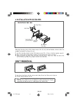
Page 16: ...vable Trim Ring Unlock Levers Carrying case 1 2 1 INSTALLATION 1 BEFORE INSTALLATION When mounting the unit in a car keep the unit as level as possible If the unit must be mounted at an angle due to the design of the vehicle make sure the unit does not tilt by more than 30 max 30 Not used FXD 785GD_body 8 6 03 10 05 PM 15 ...

Page 17: ...console 2 Bend the mounting bracket stopper outward until the bracket fits snugly in the cutout 3 Attaching the Mounting Strap to the underside of the dash board using screw Attach the back of the unit to the Mounting Strap using support stem bolt and hardware UNIT REMOVAL 1 Insert the unlock levers into the slots on each side of the unit until they click into place 2 Pull the levers to remove the...

Page 18: ...ch speaker terminal All speaker common wires must remain floating 1 Antenna socket Insert the plug from the antenna installed in your vehicle into this socket If your vehicle has a dual antenna system a dual antenna to single antenna cable adaptor may be required 2 12V Constant Power Supply Yellow Connect this wire to the 12V power terminal which receives power continuously 3 12V Accessory Switche...

Page 19: ...ion REPLACING THE FUSE When fuse replacement is necessary remove the blown fuse by using pliers Then install the new 10 amp fuse LINE OUT CONNECTIONS The unit has a line out terminals You can use a separate rear channel amplifier to upgrade your system External Amplifier Rear Speaker White Left Red Right RCA Line out Jacks RCA Line out Jacks For Rear Speakers Connect a patch cable not supplied fro...

Page 20: ...SANYO Electric Co LTD Printed in Singapore Issue date 08 03 288F0820 FXD 785GD_Cover 8 6 03 10 07 PM 2 ...

Reviews: