background image

General Installation Manual 

© July 1, 2008.  SANYO Energy (USA) Corp.  All Rights Reserved. 


Module Terminations 


A  junction  box  as  a  terminal enclosure 
is equipped for electrical connections.   


Modules  are  equipped  with  MC4

TM


locking  plugs  as  a  terminal  enclosure. 
Use  these  MC4

TM

  locking  plugs  for 

electrical connections.   

 
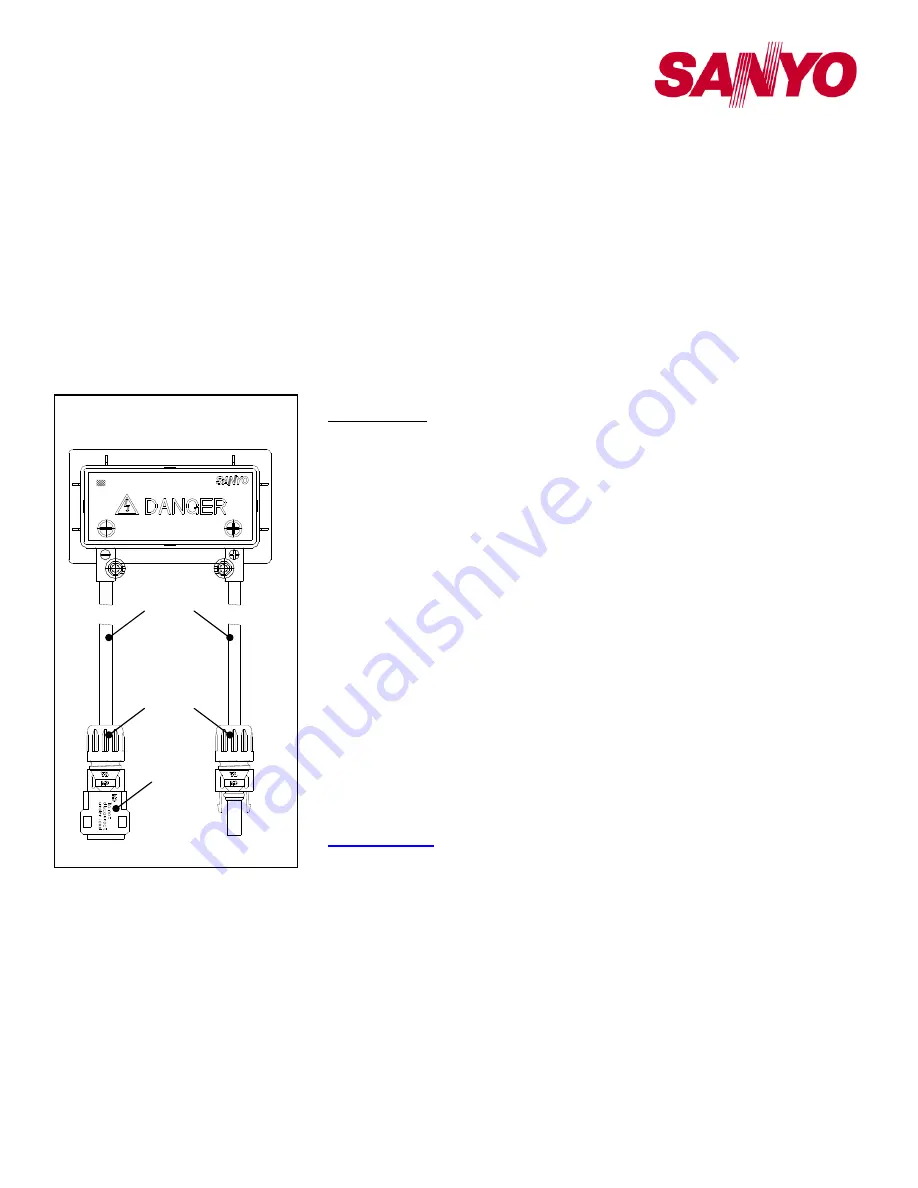
Junction Box and Terminals 


Modules  are  equipped  with  one 
junction  box  and  contain  terminals  for 
both positive and negative polarity, and 
bypass diodes. 


One  terminal  is  dedicated  to  each 
polarity;  with  the  polarity  symbols 
engraved onto the body of the junction 
box (see Figure 4). 


Conduit 


For  applications  where  wire  conduits 
are  used,  follow  the  applicable  codes 
for  outdoor  installation  of  wires  in 
conduits.  


Verify  that  all  fittings  are  properly 
installed  to  protect  wires  against 
damage and prevent moisture intrusion.  


Bypass Diodes 


When  modules  in  series  strings  are 
partially  shaded,  it  may  cause  reverse 
voltage  across  the  cells  or  modules, 
because the current from other cells in 
the  same  series  is  forced  to  flow 
through  the  shaded  area.    This  may 
cause undesirable heating to occur.  


The  use  of  a  diode  to  bypass  the 
shaded area can minimize both heating 
and array current reduction. 


Modules  are  equipped  with  factory 
installed  bypass  diodes.  The  factory 
installed  diodes  provide  proper  circuit 
protection  for  the  systems  within  the 
specified  system  voltage,  so  that  you 
do  not  need  any  other  additional 
bypass diodes. 


MAINTENANCE 


Some maintenance is recommended to 
maintain optimal output performance of 
the solar modules.  


If  the module surface becomes  dirty,  it 
may reduce output power.  


It is recommended to clean the surface 
of  the  module  with  water  and  a  soft 
cloth or sponge, twice or more per year.  


A  mild  non-abrasive  detergent  may  be 
applied for persistent dirt.   


It  is  also  recommended  to  inspect  the 
electrical  and  mechanical  connections 
annually. 


If  you  need  electrical  or  mechanical 
inspection


or


maintenance,  have  a 

licensed  authorized  professional  carry 
out  the  inspection  or  maintenance  to 
avoid  the  hazards  of  electric  shock  or 
injury. 

 
As  part  of  SANYO‘s  policy  of  continuous 
improvement,  SANYO  reserves  the  right  to 
change  product  specifications  at  any  time 
without prior notice.  
 

For  further  information,  please  visit 

sanyo.com/solar

 or contact your SANYO 

Authorized Representative. 


Cable 

Connector 
MC

 TM 

Plug


Option :  
Safety lock clip 

Figure 4   Configuration of 

Junction Box 

negative ( - ) 

positive ( + ) 

Summary of Contents for HIT Power 205 HIP-205BA19

Page 1: ...g installation and handling Work only in dry conditions with dry modules and insulated tools Do not stand or step on a module Do not puncture cut scratch or damage the back sheet of a module Back sheet damage will void a module s Limited Warranty and may cause fire Never use modules with a damaged back sheet Do not allow children and unauthorized persons near the installation or storage site of mo...

Page 2: ...not be installed nor operated in areas where salt hail snow sand dust air pollution chemically active vapors acid rain soot etc are excessive The ambient temperature must be within 20 C 4 F to 46 C 115 F The temperature limits are defined as the monthly average high and low of the installation site The wind pressure load of the installation site should be less than 2 880N m 2 60PSF SPECIFICATIONS ...

Page 3: ...ly Corrosion can be caused by the effects of weather humidity dirt and so on Corrosion can also be caused when two dissimilar metals contact each other galvanic action The module frame material is aluminum magnesium alloy All fasteners nuts bolts washers screws etc must be stainless steel unless otherwise specified Length of self tapping screws or bolts should not be more than 0 78in 20mm in order...

Page 4: ...nd around the bolt Glass Backsheet Flat washer Stainless steel Cup washer Terminal cup Stainless steel or brass Frame Longer side Ground wire 12AWG wound around the screw Flat washer Stainless steel Spring washer Stainless steel Self tapping screw Stainless steel 10 32 Ground hole 0 165 diameter 4 2 mm Glass Length not less than 0 47 12 mm not more than 0 78 20 mm Back sheet Flat washer Stainless ...

Page 5: ... of a diode to bypass the shaded area can minimize both heating and array current reduction Modules are equipped with factory installed bypass diodes The factory installed diodes provide proper circuit protection for the systems within the specified system voltage so that you do not need any other additional bypass diodes MAINTENANCE Some maintenance is recommended to maintain optimal output perfo...

Page 6: ...ll HIT Power Models HIP xxxBA19 Dimensions in mm Ground 4 places Junction Box Label Connector MC TM Plug Negative Positive Section A A Section B B Note A module should be installed on a mounting structure rail using four 4 symmetrical mounting points within Range A Range A Front Side Backside Mount Locations 63cm 24 8in 78cm 30 7in ...

Reviews: