3-14
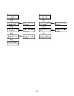
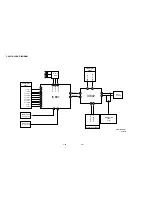
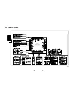
3. Y/C CIRCUIT
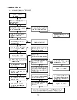
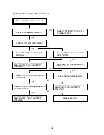
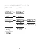
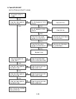
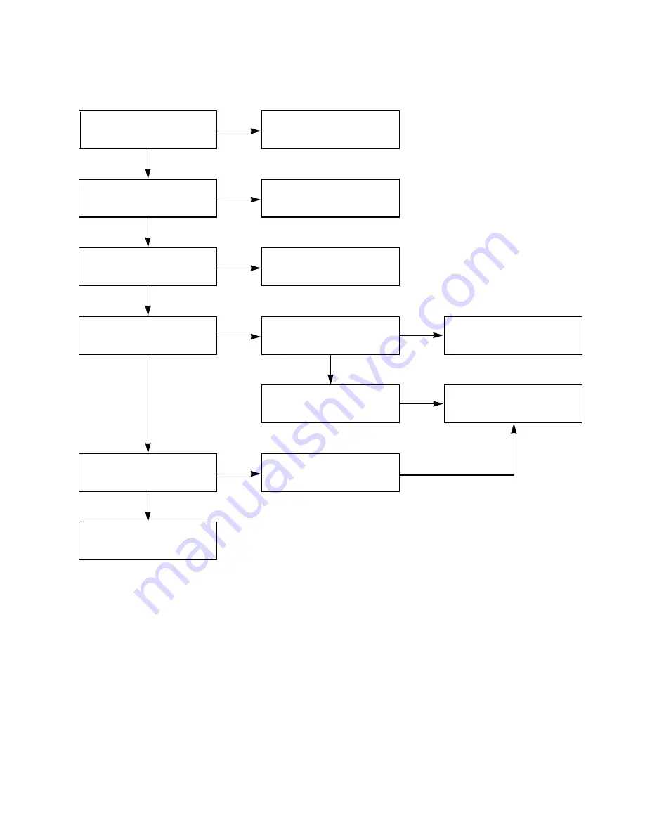
(4) When the Video signal doesn’t appear on the screen in REC Mode,
Is the EE signal normal?
Is 5.2VT/5.3VA applied to the
IC301 Pins24,42,55,72,91?
Does the RF signal appear
at the IC301 Pin78?
Check EE Mode.
Check the System of REC
‘H’. (the IC501 Pin47
/ the D301)
Replace the IC301.
Check the line of the 5.2VT/
5.3VA Line.(Power Circuit)
Check PB Mode.
Is the REC ‘H’ signal
(about 4V) applied to the
IC301 Pin80?
Check the circuit of the
IC301 Pins85, 86.
Check REC Luminance
Pass & Color Pass.
Does PB Mdoe operate
normally?
Does the REC RF signal
appear at the IC301
Pins88,89,94,95?
Check the Drum &
Drum Connector
YES
YES
YES
YES
YES
NO
NO
NO
NO
NO
NO
YES
YES
YES
Summary of Contents for HV-DX2E
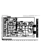
Page 36: ...3 32 3 33 2 TU IF NICAM A2 CIRCUIT DIAGRAM EE MODE VIDEO TU MODE AUDIO COMBI SCART SANYO ...
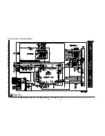
Page 41: ...3 42 3 43 7 TIMER CIRCUIT DIAGRAM SRC1203 SRC1203 LD601 C6G1 C6G2 100M 100M ...
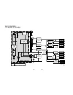
Page 45: ...3 50 3 51 PRINTED CIRCUIT DIAGRAMS 1 MAIN P C BOARD LOCATION GUIDE ...
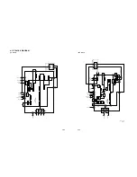
Page 64: ... 02 12 04 R17149A COMBI SCART SANYO DAP202K 3 76 3 77 6 JACK CIRCUIT DIAGRAM ...
Page 69: ...LOCATION GUIDE 3 86 3 87 PRINTED CIRCUIT DIAGRAMS 1 MAIN P C BOARD TOP VIEW ...
Page 70: ...LOCATION GUIDE 3 88 3 89 2 MAIN P C BOARD BOTTOM VIEW ...

