1-5
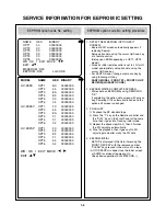
SERVICE INFORMATION FOR EEPROM IC SETTING
MODEL
NAME
HEX
BINARY
HV-DX2E
OPT1
BC
00000000
OPT2
45
00000000
OPT3
8A
00000000
OPT4
E3
00000000
OPT5
00
00000000
OPT6
04
00000000
HV-DX2EV
OPT1
FC
00000000
OPT2
45
00000000
OPT3
8A
00000000
OPT4
F1
00000000
OPT5
31
00000000
OPT6
04
00000000
HV-DX2SP
OPT1
FC
00000000
OPT2
45
00000000
OPT3
82
00000000
OPT4
F1
00000000
OPT5
54
00000000
OPT6
04
00000000
WR : OK I : EXIT MOVE :
F G
EDIT :
DE
1. DETECT NEW EEPROM (OPTION EDIT
SCREEN)
- Eeprom EDIT screen automatically appears if
replacing Eeprom.
- Setup option data using the cursor Up/Down key
of a remote control.
(Setup upon BOM depending on OPT1~OPT6
model)
• Since an initial remote control is set to LG for LG
model, appropriately set option data using the
cursor Up/Down key.
• For SANYO model, change a remocon key by
using following JIG key.
SANYO MODEL : FRONT FF + FRONT CH UP
KEY(2ND)(LG/SANYO CODE)
2. EEPROM WRITED COMPLETE SCREEN
- Writes data on EEPROM by using REMOCON
"OK".
- If completing the option data screen with a menu
key, Powering Off is automatically done and the
option edit screen is arranged.
3. PG ADJUST
1) Payback the SP standard tape
2) Press the “1” key on the Remote controller and
the “PLAY” key on the Front Panel at the same
time, then it goes into Tracking initial mode.
3) Repeat the above step(No.2), then it finishes
the PG adjusting automatically.
4) Stop the playback, then it goes out to PG
adjusting mode after mony the PG data.
4. EEPROM INITIAL
- SETUP is displayed in the field if pressing the
FRONT REC KEY with the remocon number
"CLEAR" key pressed in the status of no tape.
- AUTO SEARCH is done since the initial screen
of ACMS is serviced if powering On.
- Check basic operation (PLAY/RECORD...)
EEPROM option code No. setting
EEPROM option code No. setting procedure
NAME
HEX
BINARY
OPT1
00
00000000
OPT2
00
00000000
OPT3
00
00000000
OPT4
00
00000000
OPT5
00
00000000
OPT6
00
00000000
WR : OK I : EXIT MOVE :
F G
EDIT :
DE
MASKROM : R00
EEPROM : R00 LG CODE
Summary of Contents for HV-DX2E
Page 36: ...3 32 3 33 2 TU IF NICAM A2 CIRCUIT DIAGRAM EE MODE VIDEO TU MODE AUDIO COMBI SCART SANYO ...
Page 41: ...3 42 3 43 7 TIMER CIRCUIT DIAGRAM SRC1203 SRC1203 LD601 C6G1 C6G2 100M 100M ...
Page 45: ...3 50 3 51 PRINTED CIRCUIT DIAGRAMS 1 MAIN P C BOARD LOCATION GUIDE ...
Page 64: ... 02 12 04 R17149A COMBI SCART SANYO DAP202K 3 76 3 77 6 JACK CIRCUIT DIAGRAM ...
Page 69: ...LOCATION GUIDE 3 86 3 87 PRINTED CIRCUIT DIAGRAMS 1 MAIN P C BOARD TOP VIEW ...
Page 70: ...LOCATION GUIDE 3 88 3 89 2 MAIN P C BOARD BOTTOM VIEW ...


