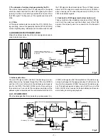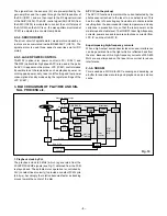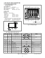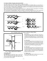
– 15 –
3-4. PW2 POWER CIRCUIT DESCRIPTION
1. Outline
This is the PW2 power circuit for iD disc drive. The oscillation
frequency is 400 kHz, and it has no voltage adjustment.
1-1. IC521
This is necessary for controlling the power supply for a PWM-
type switching regulator, and is provided with four built-in chan-
nels step-down circuits. The oscillation frequency is approx.
400 kHz.
1-2. Short-circuit protection circuit
If output is short-circuited for the length of time (approx. 120
ms) determined by the condenser which is connected to Pin
(17) of IC501, all output is turned off. The control signal (P
ON) are recontrolled or reset on the power to restore output.
1-3. 4.9 V System Power Output
CH1 is output. It is divided 4.9 V (D) and 4.9 V (A). 4.9 V (A)
is mainly used for laser power supply. Feedback for output
voltage is provided to Pin (29) of IC521 so that PWM control
can be carried out.
1-4. Analog 3.1 V System Power Output
CH2 is output. It is used for disc servo etc. of analog circuit
power supply. Feedback for output voltage is provided to Pin
(26) of IC521 so that PWM control can be carried out.
1-5. Spindle 3.35 V System Power Output
CH3 is output. It is used for spindle motor power supply. Feed-
back for output voltage is provided to Pin (11) of IC521 so
that PWM control can be carried out.
1-6. Digital 3.15 V System Power Output
CH4 is output. It is used for digital circuit power supply of
disc. Feedback for output voltage is provided to Pin (7) of
IC521 so that PWM control can be carried out.


