– 26 –
5-6. Adjust Specifications
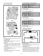
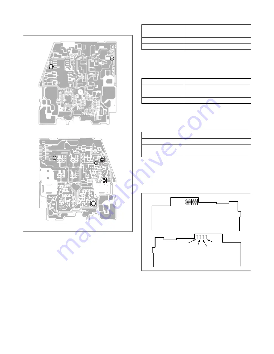
[PW1 board (Side A and B)]
Note:
1. Voltage adjustment is necessary to repair in the PW1 board
and replace the parts.
Storobe discharge:
1. Remove the solders of JW541 (pink, 330 V) and JW542
(blue, GND) on the ST1 board.
Preparation:
1. Do not activate the ST1 board when adjusting the voltage.
(If activating the circuits on the ST1 board, be sure to con-
nect a stroboscope main condenser beween JW541 and
JW542 first.)
2. Connect CN107 on the CA2 board and CN501 on the PW1
board with extension cord.
3. Connect the LCD panel and EVF panel.
4. Set the iD disc.
3. Set the power on with still mode, and set the through im-
age. (S1703 open condition.)
1. IC501 Oscillation Frequency Adjustment
Adjustment method:
1. Adjust with VR511 to 200
±
1 kHz.
2. 5.1 V (A) Voltage Adjustment
Adjustment method:
1. Adjust with VR512 to 5.15
±
0.05 V.
3. 12.4 V (L) A Voltage Adjustment
Adjustment method:
1.Adjust with VR513 to 12.40
±
0.10 V
4. Hall Element Adjustment
[CA2 board (Side A and B)]
Adjustment condition:
1. After adjustment, the readjustment is necessary to replace
the lens and the CA2 board.
Adjustment method:
1. Set the power on at the REC mode, and turn on the LCD.
2. Connect TP974 and TP972. The iris will close and get dark.
3. Adjust VR972 so that the voltage of TP971 is 1.0
±
0.03 V.
4. Disconnect TP974 and TP972, and then connect TP973
and TP972. The iris will open, and display the monitor.
5. Adjust VR971 so that the voltage of TP971 is 3.0
±
0.03 V.
Measuring Point
ADJ. Location
Measuring Equipment
ADJ. Value
CL525
Digital voltmeter
VR513
12.40
±
0.10 V
VR971
VR972
TP971
TP973 TP972
TP974
Side A
Side B
Side A
Measuring Point
ADJ. Location
Measuring Equipment
ADJ. Value
Q5109 collector or CL540
Frequency counter
VR511
200
±
1 kHz
Measuring Point
ADJ. Location
Measuring Equipment
ADJ. Value
CL529
Digital voltmeter
VR512
5.15
±
0.05 V
Side B
CL529
Q5109
CL540
CL525
VR512
VR513
VR511

