5
2
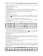
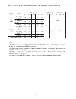
800 x 600 @ 60
40.000
37.879
60.317
3
1024 x 768 @ 60
65.000
48.363
60.004
4
1024 x 768 @ 70
75
56.48
70.07
5
1280 x 1024 @ 60
109.47
63.72
60
e). YPbPr Interface
Input YPbPr signal to YPbPr/YcbCr interface. Separately input the several types of YPbPr format
signals: 480P/60Hz, 480P/59Hz; 720P/60Hz, 720P/59Hz; 1080i/60Hz, 1080i/59Hz; 1080p/60Hz,
1080p/59Hz and check if the picture and sound is normal.
5. Preset ex-works
In the status of TV enter the factory menu by pressing the factory key and then perform presetting.
6. Ex-works packing
Check accessories and then pack them in box.
Trouble shooting
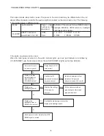
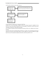
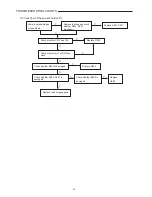
Before servicing please check to find the possible causes of the troubles according to the table
below.
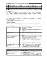
1.Antenna (signal):
Picture is out of focus or jumping
z
Bad status in signal receiving
z
Poor signal
z
Check if there are failures with the electrical connector or
the antenna.
z
Check if the antenna is properly connected.
Fringe in picture
z
Check if the antenna is correctly oriented.
z
Maybe there is electric wave reflected from hilltop or
building.
Picture is interfered by stripe
shaped bright spots
z
Possibly due to interference from automobile, train, high
voltage transmission line, neon lamp etc.
z
Maybe there is interference between antenna and power
supply line. Please try to separate them in a longer
distance.
z
Maybe the shielded-layer of signal wire is not connected
properly to the connector.
There appear streaks or light color
on the screen
z
Check if interfered by other equipment and if interfered
possibly by the equipment like transmitting antenna,
non-professional radio station and cellular phone.
2.TV set:
Symptoms Possible
cause
Unable to switch the power on
z
Check to see if the power plug has been inserted
properly into the socket.
No picture and sound
z
Check to see if the power supply of liquid crystal TV
has been switched on. ( as can be indicated by the
5
ALIGNMENT INSTRUCTION AND TROUBLE SHOOTING
LCD-20XR1AU.indd Sec1:5
LCD-20XR1AU.indd Sec1:5
2006/07/13 11:59:18
2006/07/13 11:59:18
Summary of Contents for LCD-20XR1/AU
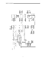
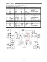
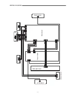
Page 13: ...11 BLOCK DIAGRAM ...
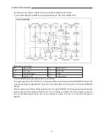
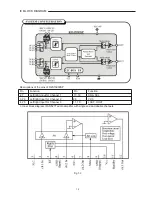
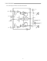
Page 16: ...14 4 Inner block diagram of TPA1517 6W stereo audio amplifier 14 IC BLOCK DIAGRAM ...
Page 23: ...21 SCHEMATIC DIAGRAM 1 INTERFACE ...
Page 24: ...22 SCHEMATIC DIAGRAM 2 TUNER AUDIO ...
Page 25: ...23 TO INFRARED BORAD SCHEMATIC DIAGRAM 3 SCALER FLI8125 ...
Page 26: ...24 SCHEMATIC DIAGRAM 4 FLASH ...
Page 27: ...25 SCHEMATIC DIAGRAM 5 OUTPUT POWER KEY BOARD ...
Page 28: ...26 SCHEMATIC DIAGRAM 6 POWER BOARD INFRARED BOARD ...
Page 29: ...27 EXPLODED VIEW 1 2 3 4 5 6 7 8 9 10 11 12 13 14 15 16 17 18 19 20 21 22 23 ...


