Sa
fe
ty
Pre
ca
ut
io
ns
:
1.
Be
su
re
to
as
k
an
au
th
or
iz
ed
se
rv
ic
e
pe
rs
on
ne
l to
ca
rr
y
ou
t se
tu
p.
2.
Th
or
ou
gh
ly
re
ad
th
is
in
st
ru
ct
io
n
be
fo
re
se
tu
p
an
d
fo
llow
th
e
st
ep
s
be
lo
w
pr
ec
is
el
y.
3.
Th
e
wa
ll
to
be
mo
un
te
d
sh
ou
ld
be
ma
de
fr
om
so
lid
ma
te
ri
al
s.
On
ly
us
e
ac
ce
ss
or
ie
s
su
pp
lied
by
th
e
ma
nu
fa
ct
ur
er
.
4.
V
er
y
ca
re
fu
lly
ha
nd
le
th
e
un
it
du
ri
ng
se
tu
p.
We
ar
e
no
t li
ab
le
fo
r
an
y
da
ma
ge
or
in
ju
ry
ca
us
ed
by
mi
sh
an
dl
in
g
or
im
pr
op
er
in
st
al
la
ti
on
.
5.
Be
su
re
to
pl
ac
e
th
e
un
it
on
a
st
ab
le
an
d
so
ft
pl
at
fo
rm
wh
ic
h
is
st
ro
ng
en
ou
gh
to
su
pp
or
t th
e
un
it
.
6.
Do
no
t up
lift
th
e
sp
ea
ke
r
wh
en
mo
vi
ng
th
e
di
sp
la
y.
Th
e
ap
pe
ar
an
ce
of
th
e
un
it
ma
y
di
ff
er
en
t fr
om
th
e
ac
tu
al
on
es
.
7.
De
si
gn
an
d
sp
ec
ific
at
io
ns
ar
e
su
bj
ec
t to
ch
an
ge
wi
th
ou
t no
ti
ce
.
8.
Ret
ai
n
th
es
e
in
st
ru
ct
io
ns
fo
r
fu
tu
re
re
fe
re
nc
e.
W
ALL
MOUNTING
INSTRUCTIONS
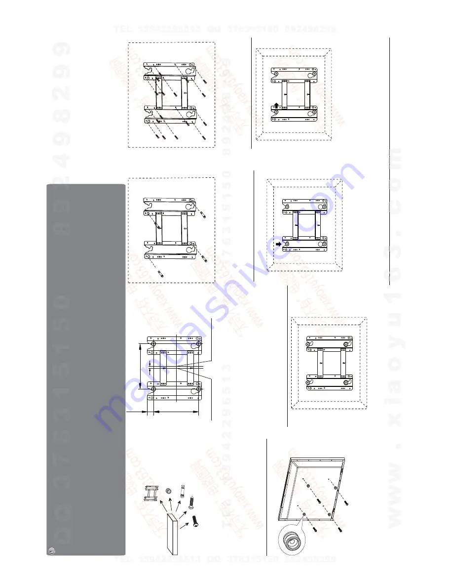
Wa
ll
2.
Du
e
to
th
e
wa
ll
mo
un
ti
ng
fi
x-
gr
oo
ve
le
an
in
g
to
th
e
ri
gh
t
si
de
,
th
e
wh
ol
e
un
it
wi
ll
le
an
to
ri
gh
t
si
de
af
te
r
in
st
al
la
ti
on
,
pl
ea
se
ca
re
fu
lly
me
as
ur
e
th
e
po
si
ti
on
of
th
e
ho
le
s
yo
u
wa
nt
to
dr
ill,
re
fe
r
to
th
e
pa
ra
me
te
rs
on
Fi
g.
2
wh
en
dr
illi
ng
th
e
ho
le
s.
No
te
:
Th
e
"X
"
in
Fi
g.
2
re
pr
es
en
ts
a
da
ta
.
It
ma
y
be
20
0m
m
or
40
0m
m
or
60
0m
m.
Fig.1
Fig.2
Fig.5
4.
Us
e
th
e
4p
cs
co
mb
in
at
io
n
sc
re
ws
to
fi
x
th
e
wa
ll
mo
un
ti
ng
co
nn
ec
to
r
to
th
e
re
ar
of
th
e
di
sp
la
y
un
it
.(
Ca
ut
io
n:
th
e
di
re
ct
io
n
of
the
connectors
should
be
strictly
co
nf
ir
m
to
th
e
di
ag
ra
m
il
lu
st
ra
te
d
ab
ov
e)
.
5.
Pu
t
th
e
ba
ck
of
th
e
di
sp
la
y
un
it
cl
os
e
to
th
e
wa
ll
mo
un
ti
ng
ho
ld
er
,
in
se
rt
th
e
fo
ur
wa
ll
mo
un
ti
ng
co
nn
ec
to
rs
in
to
th
e
fo
ur
ca
la
ba
sh
-s
ha
pe
d
ho
le
s
on
th
e
wa
ll
mo
un
ti
ng
ho
ld
er
. (F
ig
.5
)
Ta
ke
ou
t
th
es
e
pa
rt
s
fr
om
th
e
bo
x
Wa
ll
Mo
un
ti
ng
Ho
ld
er
Ex
pa
ns
io
n
Bo
lt
Wo
o
d
Sc
re
w
Co
mb
in
at
io
n
Sc
re
w
Wa
ll
Mo
un
ti
ng
Co
nn
ec
to
r
Fig.3a
Fig.4
Fig.6
Fig.7
3a
.
Sc
re
w
4p
cs
ex
pa
ns
io
n
bo
lt
s
to
fi
x
th
e
wa
ll
mo
un
ti
ng
ho
ld
er
on
th
e
wa
ll.
6.
Le
t
th
e
di
sp
la
y
un
it
sl
ow
ly
sl
id
e
do
wn
to
the
end
of
the
calabash-shaped
hole.
(F
ig
.6
)
7.
Pu
sh
ri
gh
tw
ar
ds
ca
re
fu
lly
un
ti
l
th
e
wa
ll
mo
un
ti
ng
co
nn
ec
to
rs
fu
lly
sl
id
e
in
to
th
e
ri
gh
t
fix-
gr
oo
ve
s
an
d
be
su
re
th
e
mo
un
ti
ng
is
se
cu
re
.
8.
If
yo
u
wa
nt
to
di
sm
ou
nt
th
e
un
it
do
th
e
ab
ov
e
st
ep
s
in
re
ve
rs
e
or
de
r.
(Unit:mm)
Re
ar
wall
mounting
hole
center
Wa
ll
mounting
fix-hole
center
200
27
X
8
1.
Th
er
e
ar
e
th
re
e
op
ti
on
s
of
wa
ll
mo
un
ti
ng
holder
with
different
specifications
:2
00
20
0,
20
04
00
,2
00
60
0.
Pl
ea
se
ch
ec
k
yo
ur
wa
ll
mo
un
ti
ng
ho
ld
er
fo
r
it
s
sp
ec
ific
at
io
n.
Wa
ll
Fig.3b
3b
.
If
yo
ur
wa
ll
is
a
wo
od
en
st
ru
ct
ur
e,
pl
ea
se
fix
th
e
wa
ll
mo
un
ti
ng
ho
ld
er
on
th
e
wa
ll
wi
th
16
pc
s
wo
od
sc
re
ws
.
Note:
All
the
wall
mounting
parts
are
optional
and
may
be
unavailable
in
your
model.
Below
we
will
show
you
how
to
mount
the
Display
on
the
wall
using
our
company
’s
wall
mounting
components.
di
sp
la
y
u
co
n
n
e
n
it
(C
ut
i
o
rs
sh
o
n
th
e
di
u
ld
b
e
tl
y
mo
co
ti
n
ct
ho
ld
e
rs
in
to
in
se
rt
e
fo
ur
h
e
fo
u
ba
s
5
wa
m
ape
d
n
ti
ng
on
8I
f
wa
di
he
u
ot
h
y
.Be
su
r
Th
or
o
to
k
a
gh
ly
re
a
zed
n
st
ru
ce
be
on
ne
lt
etu
p
a
ry
rr
o
fo
llow
etu
p
tep
o
w
p
y
ts
a
b
le
g
p
a
va
i
o
u
n
b
e
u
w
a
ll
m
a
y
l
th
a
n
d
e
:
ti
o
n
a
N
o
re
ig
.
th
re
e
op
of
wa
l
mo
ti
g
2.
Du
e
o
th
e
w
l
m
o
un
g
turur
ee
tru
d
en
g
wo
o
is
a
wa
l
oo
uur
If
3
h
e
fix
to
bo
lt
o
n
g
pa
n
s
e
4
c
ere
ww
o
th
e
Summary of Contents for LCD-42XR8KH
Page 11: ...9 2 TDA4470 2 2 TDA4470 ...
Page 13: ...11 ...
Page 20: ...MIAN BOARD ...
Page 21: ...MIAN BOARD ...
Page 22: ...MIAN BOARD ...
Page 23: ...MIAN BOARD ...
Page 24: ...MIAN BOARD ...
Page 25: ...MIAN BOARD ...
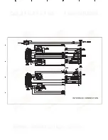
Page 26: ...INTERFACE CONNECTION ...
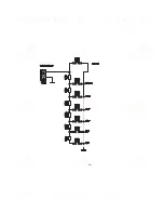
Page 27: ...KEY ...
Page 28: ...IR ...
Page 29: ...POWER ...
Page 31: ...APPENDIX B Exploded view LCD 42XR8KH APPENDIX B Exploded v view LCD 42 ...
Page 36: ...June 2009 ...


