background image


Fig2 Device EN25B52 successful connection   
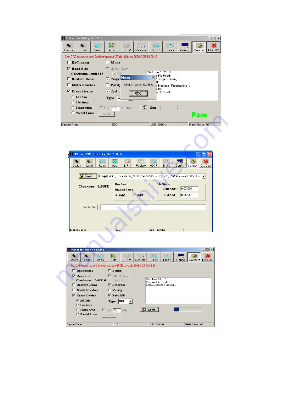
 
(3) 

Click “Read” and select the file written (MERGE.bin for example) as shown in fig3.   


Fig3 the written file 

(4) 

Click “Auto”, select “All chip” , “program” and other items as shown if fig4. 


Fig4 selected items 

 
(5) 

Press “Run” in fig4 to begin writing and there are two steps: Erase and Program. 
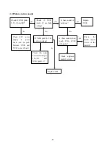
(6) 

If the process of writing succeeds, it will display “Pass” near “Run” as shown in fig5.   

Summary of Contents for LCD-47XR8DA

Page 1: ...LCD 47XR8DA 1 682 344 41 CCIR DVB T SM0915046 ...

Page 2: ...ware upgrading Working principle analysis of the unit Block diagram IC block diagram Wiring diagram Troubleshooting guide Schematic diagram APPENDIX A Assembly list APPENDIX B Exploded View 1 3 11 12 13 18 19 24 Removing or Installing the Stand Wall mounting instructions ...

Page 3: ... will result 2 5 If any foreign substance such as water liquid metal slices or other matters happens to fall into the module be sure to cut the power off immediately and do not move anything on the module lest it should cause fire or electric shock due to contact with the high voltage or short circuit 2 6 Should there be smoke abnormal smell or sound from the module please shut the power off at on...

Page 4: ...20 85 Scope for storage 10 90 2 13 Display of a fixed picture for a long time may result in appearance of picture residue on the screen as commonly called ghost shadow The extent of the residual picture varies with the maker of LCD screen This phenomenon doesn t represent failure This ghost shadow may remain in the picture for a period of time several minutes But when operating it please avoid dis...

Page 5: ...e 8 55 9 45V 0 4 85 5 35V 0 11 4 12 6V 0 4 85 5 35V 0 2 5 b Test the pin voltage of XV01 the data is shown in table2 Table2 voltage data of XV01 XV01 Pin1 2 3 4 5 Voltage 23 8 25 2V 0 c Test the pin voltage of X101 the data is shown in table3 Table3 voltage data of X101 X101 Pin1 2 Voltage 31 4 32 6V 0 3 Alignment flow chart The alignment flow chart is shown as fig 1 Check if DDC HDCP KEY FLASH ar...

Page 6: ...en preset ex factory unless the client appointed it k ISP Mode ON soft upgrading through VGA port with ISP device OFF DDC function of VGA the setting will not be memory and will be OFF when power on again l REST ALL initialization of the factory and user data after this item is confirm the unit will restart and display the guiding image m Factory Data Reset factory data initialization including wh...

Page 7: ...n YPbPr channel a Switch to YPbPr channel b Press SOURCE then press 2 5 8 0 in turn to enter the level one factory menu c Move the cursor to ADC ADJUST and press OK to enter the sub menu d Input YPbPr signal VG 848 Timing 978 483P Pattern 984 SMPTE Color Bar Move the cursor to mode press CH and CH to select YPbPr HD move the cursor to AUTO ADC and press ENTER to adjust automatically till complete ...

Page 8: ... Y coordinate data while lower G gun to decrease the data G gun adjustment will affect Y and Lv greatly 5 Performance check 5 1 TV function Connect RF to the center signal source enter Channel menu auto search check if there are channels be skipped check if the picture and speaker are normal 5 2 AV S Video terminals Input AV S Video signal check if the picture and sound are normal 5 3 YPbPr YcbCr ...

Page 9: ...79 60 317 40 VESA 7 800X600 48 077 72 188 50 VESA 8 800X600 46 875 75 49 5 VESA 9 1024X768 48 363 60 004 65 VESA 10 1024X768 56 476 70 069 75 VESA 11 1024X768 60 023 75 029 78 75 VESA 12 1152X864 67 5 75 108 VESA 13 1280X960 60 60 108 VESA 14 1280X1024 63 98 60 02 108 VESA 15 1280X1024 80 75 135 SXGA 16 1440X900 60 17 1680X1050 60 18 1360X768 47 7 60 85 5 5 5 HDMI terminal Input HDMI signal VG849 ...

Page 10: ...Yes NA04 5272402002 AT24C02 HDMI EDID Yes NA08 5272402002 AT24C02 HDMI EDID Australia only Yes N107 5272421002 AT24LC21A VGA EDID Yes Written with device like ALL11 Note1 write protect setting enter ALL 100 interface select Config and press config setting set Protect to All Protect select config when writing The write protect will be set again when ALL 100 program restart Note2 software writing an...

Page 11: ... example as shown in fig3 Fig3 the written file 4 Click Auto select All chip program and other items as shown if fig4 Fig4 selected items 5 Press Run in fig4 to begin writing and there are two steps Erase and Program 6 If the process of writing succeeds it will display Pass near Run as shown in fig5 ...

Page 12: ...SB device 3 Insert the USB device to USB port of the unit power on and select RF ATV channel begin USB upgrade after OSD disappear It will display blue when read the data from USB device while display red when write Flash The flash must be pull out when display red It will flicker in red and blue if the process of writing is abnormal 4 The method are not applicable to all the USB devices try anoth...

Page 13: ...or panel display HD audio signal via decoder built in MSD109 resumed to multi channel sound of Dolby AC 3 The audio signal will be sent to back end to perform bass adjustment and volume control then it will separate into L R channels and input to earphone amplifier BH3547F amplifying then output two ways One way will be sent to earphone another way will be sent to digital sound amplifier R2A15112F...

Page 14: ...er control IC MSD109 to digital decode image scale and OSD superposition then output LVDS drive level for panel display HDMI audio signal via decoder built in MSD109 is fed to back end to bass adjust and volume control the sound will separate into L R channels and input to earphone amplifier BH3547F amplifying then output two ways One way will be sent to earphone another way will be sent to digita...

Page 15: ...Supports HDTV RGB YPbPr YCbCr Supports Composite Sync and SOG Sync on Green separator Automatic color calibration DVI HDCP HDMI input ports Supports up to 225MHz 1080P 60Hz with 12 bit deep color resolution High bandwidth Digital Content Protection HDCP 1 1 compliant receiver High Definition Multimedia Interface HDMI 1 3 compliant receiver with CEC Consumer Electronics Control support Video Proces...

Page 16: ...th SAW and supports demodulation of 6MHz 7MHz and 8MHz 2K 8K carrier and supports both serial and parallel TS stream output 3 R2A10406NP VIF frequency corresponds to 38 9MHz SIF frequency corresponds to M N B G I D K and SECAM L L I2CBUS control ...

Page 17: ...15 4 PS321 The chip supports both I2C control and I O control mode supports both internal and external EDIT 5 R2A15112FP ...

Page 18: ...16 6 TDA1616 ...

Page 19: ...17 ...

Page 20: ...18 Wiring diagram data board power board panel IR key board speaker power switch adjustment port back light board ...

Page 21: ...nterfered by other equipment and if interfered possibly by the equipment like transmitting antenna non professional radio station and cellular phone 1 2 TV set Symptoms Possible cause Unable to switch the power on Check to see if the power plug has been inserted properly into the socket No picture and sound Check to see if the power supply of liquid crystal TV has been switched on As can be indica...

Page 22: ...ot work properly Check if the batteries are installed in the reverse order Check if the battery is effective Check the distance or angle from the monitor Check if there is any obstruct between the remote control and the TV set Check if the remote control signal receiving window is exposed to strong fluorescence No picture and sound but only hash Check if the antenna cable is correctly connected or...

Page 23: ... STANDBY circuit of power supply board Press POWER button on the unit or sensor control and check the indicator Check if the PIN3 of X804 on main board is high level Check if the PIN11 of X802 on main board is high level Check power supply board Check power board and back light board yes no no red blue yes Check the backlight control circuit on the main board no yes ...

Page 24: ...ration Check if all channels have no signal Replace main board Enter factory menu initialization EEPROM then turn off the TV turn on again display picture Adjust main board again Replace main board no yes yes no yes Does display OSD menu on screen when press menu button yes no no ...

Page 25: ... board Is there sound in earphone Is there sound when touch CV04 CV05 with probe Check earphone amplify circuit Replace NV02 Check the audio output circuit of the main IC no yes no yes yes yes no Check if NV02 pin10 27 are high voltage If NS01 pin126 148 are low voltage no Check the path between NS01 pin 126 148 and NV02 pin10 27 Replace NS01 ...

Page 26: ......

Page 27: ......

Page 28: ......

Page 29: ......

Page 30: ......

Page 31: ......

Page 32: ......

Page 33: ......

Page 34: ......

Page 35: ......

Page 36: ...sing XI6HE0206910 NS01 MSD109CL 5270109001 board N101 R2A10406NP 5271040601 NJ01 CE6353 5276353001 NA05 PS321TQF 5270321001 NV02 R2A15112FP 5271511201 IR board XI6HU0280910 Keyboard XI6HU0300510 Power board XI6FN0132010 Remote control XI6010J01701 RC J17 0A Panel XI5203478503 V470H1 L03 ...

Page 37: ...DA No Description 1 2 3 4 5 6 7 8 9 Speaker connector Front cabinet Panel Panel connector Frame IR board Digital processing board Part list Rear terminal cover Keyboard 10 Power switch Back cabinet 11 12 13 14 Speaker Stand Power board ...

Page 38: ...fixer 8 6 Frame 1 7 XI6HU0280910 IR board 1 8 XI6HE0206910 Digital processing board 1 9 XI5831000G10 Rear terminal cover 1 10 XI6HU0300510 Keyboard 1 11 XI5HW27RI02D Back cabinet 1 12 XI6170692060 Speaker 2 13 XI6151071540 Stand 1 14 XI6FN0132010 Power board 1 15 XI5944033680 User manual 1 16 XI6010J01701 Remote control 1 RC J17 0A Note Only the parts in above list are used for repairing Other par...

Page 39: ...Make sure that you put down a soft cushion or cloth so that your TV is not scratched 2 Align the stand column with the hole in the TV back and then secure the stand to the TV with nine screws M4x40 Please note the stand s front and back otherwise the TV may be unstable and tip over Note Removing or Installing the Stand Cautions 1 Carefully handle the unit during setup and consult authorized servic...

Page 40: ...ctor to the rear of the display unit Caution the direction of the connectors should be strictly confirm to the diagram illustrated above 5 Put the back of the display unit close to the wall mounting holder insert the four wall mounting connectors into the four calabash shaped holes on the wall mounting holder Fig 5 Take out these parts from the box Wall Mounting Holder Expansion Bolt Wood Screw Co...

Page 41: ...9247HE2710 Ver 1 0 ...

Reviews: