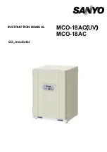
background image

MCO-18AC

(

UV

)

MCO-18AC 

INSTRUCTION MANUAL


CO

2

 Incubator


Summary of Contents for MCO-18AC UV

Page 1: ...MCO 18AC UV MCO 18AC INSTRUCTION MANUAL CO2 Incubator ...

Page 2: ...5 5 Keihan Hondori 2 Chome Moriguchi City Osaka 570 8677 Japan Printed in Japan 7FB6P101567000 29 June 2010 ...

Page 3: ...VS3 P 19 Precautions when using the UV lamp P 20 Setting the UV lamp ON period P 21 Lighting the UV lamp for 24 hours P 22 KEY LOCK FUNCTION P 23 WATER LEVEL SENSOR MCO 18AC UV or MCO 18AC with MCO 18UVS3 P 24 ALARMS SAFETY AND SELF DIAGNOSIS P 25 SETTING OF ALARM RESUME TIME P 26 Operation after power failure P 26 ROUTINE MAINTENANCE Cleaning the chamber and inner attachments P 27 Filling the hum...

Page 4: ...l will be subjected to change without notice due to the improvement of performance or functions Contact Sanyo sales representative or agent if any page of the manual is lost or page order is incorrect Contact Sanyo sales representative or agent if any point in this manual is unclear or if there are any inaccuracies No part of this manual may be reproduced in any form without the expressed written ...

Page 5: ...ymbol shows this symbol means caution this symbol means an action is prohibited this symbol means an instruction must be followed Be sure to keep this manual in a place accessible to users of this unit Label on the unit This mark is labeled on the cover in which the electrical components of high voltage are enclosed to prevent the electric shock The cover should be removed by a qualified engineer ...

Page 6: ...y outlet is not grounded it will be necessary to install a ground by qualified engineers Never ground the unit through a gas pipe water main telephone line or lightning rod Such grounding may cause electric shock in the case of an incomplete circuit Connect the unit to a power source as indicated on the rating label attached to the unit Use of any other voltage or frequency other than that on the ...

Page 7: ...sconnect the power supply plug if there is something wrong with the unit Continued abnormal operation may cause electric shock or fire When removing the plug from the power supply outlet grip the power supply plug not the cord Pulling the cord may result in electric shock or fire by short circuit Disconnect the power supply plug before moving the unit Take care not to damage the power cord A damag...

Page 8: ... be damaged due to the change of setting Be careful not to tip over the unit during movement to prevent damage or injury Prepare a safety check sheet when you request any repair or maintenance for the safety of service personnel LABELS ON THE INCUBATORS Warning and caution labels are attached to the incubator The following table describes the labels This label is attached to covers that access hig...

Page 9: ...dity 80 for temperature up to 31o C decreasing linearly to 50 relative humidity at 40o C Mains supply voltage fluctuations not to exceed 10 of the nominal voltage Other supply voltage fluctuations as stated by the manufacturer Transient overvoltages according to Installation Categories Overvoltage Categories II For mains supply the minimum and normal category is II Pollution degree 2 in accordance...

Page 10: ...18AC UV or when an optional UV system kit MCO 18UVS3 is installed 2 5 6 7 8 13 9 inside Handles 1 18 3 4 Handles 10 11 14 For MCO 18AC UV or when an optional UV system kit MCO 18UVS3 is installed 21 16 15 12 17 Rear Left Side Rear Right Side 8 ...

Page 11: ... are available If MCO 21GC is not used only A is available Refer to page 14 for gas cylinder connection Ensure that the gas pressure is set at 0 03 MPaG 0 3 kgf cm2 G 4 3 psiG Refer to page 39 for automatic CO2 cylinder changeover system 13 Door switch Detects the door opening closing and stops the circulating fan UV lamp and electromagnetic valve for CO2 when door is open 14 Humidifying pan Use s...

Page 12: ...emperature reaches the upper limit set value 8 CO2 inject lamp INJECT This lamp lights when CO2 gas is being injected 9 Digital CO2 density indicator CO2 Normally this indicator shows the CO2 concentration in the chamber In the setting mode it indicates the set value of the CO2 concentration In the calibration mode the decimal point in the digital CO2 density indicator blinks 10 Set key SET Pressi...

Page 13: ...this key in the setting mode causes the numerical value to shift In key lock mode pressing this key makes key lock ON or OFF See page 23 for details 17 Digit shift key Pressing this key in the setting mode causes the changeable digit to shift Pressing this key more than 5 seconds enters key lock mode See page 23 for the key lock Remote alarm terminal The terminal of the remote alarm is installed a...

Page 14: ...p the ambient temperature in adequate range A location with a sturdy and level floor Always install the incubator on a sturdy and level floor The uneven floor or tilted installation may cause failure or injury Install the incubator in stable condition to avoid the vibration or noise Unstable condition may cause vibration or noise WARNING Install the incubator on a sturdy floor If the floor is not ...

Page 15: ...ly outlet is not grounded it is necessary to install a ground by qualified engineers Never ground the incubator through a gas pipe water main telephone line or lightning rod Such grounding may cause electric shock in the case of an incomplete circuit Stacked module When the product is used in stacked module make sure to fix the incubator by using the stacking kit WARNING Do not climb onto the incu...

Page 16: ... an explosive sound When the MCO 21GC is not mounted Using the gas supply pipe that is provided connect the CO2 gas pressure regulator for the CO2 gas cylinder to CO2 gas pipe connection port A on the incubator After connecting the pipe check to make sure that no gas is leaking When the MCO 21GC is mounted Connect a pair of CO2 gas cylinders with CO2 gas pressure regulators independently The gas s...

Page 17: ...th a sterile dry gauze Especially when the culture medium is spilled clean and disinfect the chamber immediately Refer to page 27 Routine maintenance for details Keep the inside panels dry To protect the inside of the incubator from contamination the inside panels should always be kept dry If water is spilled from a humidifying pan or if the door is kept open for a long period condensation will fo...

Page 18: ...tely and then shut the outer door If the inner door is not closed completely even if the outer door is closed the incubator will fail to exhibit its maximum performance And close the doors gently Rude closing may cause spillage of medium incomplete closing or damage of gasket Open close the doors gently Ensure you close the doors gently Robust closing may cause spillage of medium incomplete closin...

Page 19: ...attachments on page 27 3 Add approximately 1 5 L of sterile distilled water to the humidifying pan Refer to page 30 4 Turn ON the power switch on the rear left side Note The humidity in the incubator chamber is adjusted to the optimum setting To prevent condensation on the surface inside chamber and the inner door there is a low temperature area under the humidifying pan in the bottom of chamber t...

Page 20: ...sing numerical value shift key and digit shift key set the figure to 37 0 When pressed the figure of settable digit changes 4 Press enter key ENT Set temperature is memorized Left digit in the digital CO2 density indicator blinks When pressed the changeable digit is shifted 5 By pressing digit shift key and numerical value shift key set the figure to 05 0 When pressed the figure of settable digit ...

Page 21: ...own in the page 21 If the outer door is not opened for at least 12 consecutive hours the UV lamp will light for the preset time period every 12 hours The period can be changed when necessary as shown in the page 21 When checking the UV lamp operation open the outer door and push the door switch with the inner door closed The visible blue light can be checked under the humidifying pan cover The UV ...

Page 22: ...aping Always use them even when not humidifying To check whether the UV lamp is lit open the outer door and then press the door switch with the inner door still closed Visible blue light can be confirmed from the front of the humidifying pan cover UV light is harmful to the eyes so do not light the UV lamp when the inner door or humidifying pan cover is open Be careful when handling the UV lamp Th...

Page 23: ...er key ENT Set value is memorized and the display return to normal display mode The UV timer can be set from 0 to 30 min The default setting is for 5 min When the UV timer is set to zero the UV lamp will not light If the outer door is opened while the UV lamp is lit the lamp will turn OFF Then when the door is closed the lamp will light for the preset period of time If the UV lamp ON time is set f...

Page 24: ...t the figure to 001 When pressed the figure of settable digit changes 5 Press enter key ENT Set value is memorized and the display returns to normal display mode This procedure must be preformed only with the outer door closed and the UV lamp turned OFF The UV lamp will light continuously for 24 hours after this parameter is set The setting is canceled if the outer door is opened Perform the above...

Page 25: ... setting change from key lock OFF to key lock ON Description of operation Key operated Indication after operation 1 The current chamber temperature and CO2 density are displayed 2 Press digit shift key for 5 seconds L0 is displayed in the temperature indicator 3 Press numerical value shift key and scroll the figure to 1 When pressed the figure of settable digit changes 4 Press enter key ENT The ke...

Page 26: ...e time of installation of humidifying pan check that the pan is set properly and sensor is down in the pan The water level alarm lamp RH PAN blinks if the sensor is not down completely In this case set the pan again in adequate location The sensor detects the water level every 30 minutes In addition detection is executed after operation of the outer door It takes several seconds to detect the wate...

Page 27: ...ator Ambient temperature sensor abnormality If the ambient temperature sensor is short circuited E10 is displayed alternately with the temperature on the digital temperature indicator Intermittent tone Remote alarm CO sensor 2 abnormality If the output voltage of the CO2 sensor is abnormal E11 is displayed alternately with the temperature on the digital temperature indicator Intermittent tone CO v...

Page 28: ...t changes 6 Press enter key ENT The setting is memorized and the current chamber temperature is displayed The settable alarm resume time are 0 10 20 30 40 50 or 60 minutes The setting is 000 010 020 030 040 050 or 060 respectively The buzzer would not reset if the reset time is set in 000 It is recommended to set the alarm resume time when the incubator is not under alarm condition The setting dur...

Page 29: ...s from sharp edges or corners Note Be careful not to damage the water level sensor or the UV lamp in the chamber duct if the MCO 18AC UV or an optional UV system kit MCO 18UVS3 is installed Do not use detergents or antiseptic solutions with acid alkali or chlorine Doing so may cause discoloration corrosion or rusting 1 Close the valve of the CO2 gas cylinder and turn off the power to the incubator...

Page 30: ...rew securing the clamp for the side support and remove the clamp See Fig 8 11 Lift the side support off of the pins See Fig 9 Fig 7 Fig 8 Fig 9 Clamp support Side Fan 12 Clean all the attachments with a diluted neutral detergent and then rinse them thoroughly with distilled water 13 Wipe the trays the inner attachments such as the fan and the chamber sides with sterilizing alcohol Be careful not t...

Page 31: ... the procedure in reverse order from step 11 17 Fill the humidifying pan with sterile distilled water Note When installing the fan insert it securely on the motor shaft See Fig 10 Lightly turn the fan manually to make sure that it does not strike the rear panel Improper insertion may cause poor performance As shown in Fig 11 set the tray with only the front edge bent down If the tray is set in the...

Page 32: ...w temperature water will lower the temperature and humidity in the chamber 5 Set the humidifying pan with the inner side flush against the back and close the inner and outer doors MCO 18AC UV or when an optional UV system kit MCO 18UVS3 is installed Set the humidifying pan with the inner side flush against the back and replace the humidifying cover Refer to page 24 Close the inner and outer doors ...

Page 33: ...ift key then press the enter key ENT 4 The incubator automatically reverts to the display mode Example If the displayed chamber temperature is 37 0o C set value and the actual temperature is 36 8o C 1 Press the calibration key CAL for about 5 seconds 2 The 3 on the digital temperature indicator blinks and the digital CO2 density indicator goes out 3 Adjust the set value to the actual value of 36 8...

Page 34: ...ing of CO2 density is 2 or more Example For an internal CO2 density of 5 0 setting and a measured value of 4 5 1 Press the calibration key CAL once 2 Press the calibration key CAL for about 5 seconds again 3 The 3 on the digital temperature indicator blinks and the digital CO2 density indicator goes out 4 Press the calibration key CAL once again 5 The 0 on the digital CO2 density indicator blinks ...

Page 35: ...qual to the set temperature The ambient temperature must always be at least 5o C less than the set temperature The outer door was closed while the inner door was left open If the CO2 gas density does not coincide with the set value The secondary pressure is not set to 0 03MPaG 0 3kgf cm2 G 4 3psiG The gas tube is clogged or chinked The humidifying pan is not filled with sterile distilled water Alw...

Page 36: ... disposing of the CO2 incubator contact a Sanyo sales representative or agent WARNING The incubator must be dismantled and disposed of by qualified personnel only If the incubator is left where outsiders enter it may result unexpected accident for example children to become locked inside Before disposing a CO2 incubator with biohazardous danger decontaminate the CO2 incubator to the extent possibl...

Page 37: ...lection recycling centre In the European Union there are separate collection systems for used electrical and electronic products Please help us to conserve the environment we live in German Ihr SANYO Produkt wurde entworfen und hergestellt mit qualitativ hochwertigen Materialien und Komponenten die recycelt und wiederverwendet werden können Dieses Symbol bedeutet daß elektrische und elektronische ...

Page 38: ...nière inappropriée peuvent s avérer potentiellement dangereuses pour la santé humaine et pour l environnement Cependant ces matières sont nécessaires au bon fonctionnement de votre appareil ou de votre machine Pour cette raison il vous est demandé de ne pas vous débarrasser de votre appareil ou machine usagé avec vos ordures ménagères Spanish Los productos SANYO están diseñados y fabricados con ma...

Page 39: ... recolha separados para produtos eléctricos e electrónicos usados Por favor ajude nos a conservar o ambiente em que vivemos Italian Il vostro prodotto SANYO è stato costruito da materiali e componenti di alta qualità che sono riutilizzabili o riciclabili Prodotti elettrici ed elettronici portando questo simbolo alla fine dell uso devono essere smaltiti separatamente dai rifiuti casalinghi Vi pregh...

Page 40: ...nische apparatuur bij de daarvoor wettelijke instanties aangeboden Alstublieft help allen mee om het milieu te beschermen Swedish Din SANYO produkt är designad och tillverkad av material och komponenter med hög kvalitet som kan återvinnas och återanvändas Denna symbol betyder att elektriska och elektroniska produkter efter slutanvändande skall sorteras och lämnas separat från Ditt hushållsavfall V...

Page 41: ...CO 21GC detects that there is no more CO2 gas in a cylinder when the CO2 density in the chamber does not increase for a while even after opening the CO2 gas valve in the incubator It switches the gas supply line when it detects that there is no more gas At that time the following indications of switching the gas cylinder are provided CO2 gas supply line indicator Digital temperature indicator Buzz...

Page 42: ...ottom and attach the protective stickers to the four corners on the top surface of the incubator that is to be on the bottom See Fig A on the page 41 4 Secure stacking plates A with the screws that are provided 5 Remove the front panel 4 screws from the incubator that is to be on the top 6 Place the upper incubator on top of the lower one being careful not to pinch your fingers 7 Make the lower in...

Page 43: ...Stacking plate A Protective sticker Hook Stacking plate B Front side Front panel Fig A 41 ...

Page 44: ... UV lamp 4W X 1 ozone free emission Water level sensor Optical type UV lamp failure alarm Low humidifying water alarm Alarm Automatic set temperature alarm Automatic set CO2 density alarm Upper limit temperature alarm various gas sensor heater alarms Remote alarm contact Allowable contact capacity DC 30 V 2 A CO2 inlet connection 4 to 6 mm diameter tube can be connected CO2 inlet pressure 0 03MPaG...

Page 45: ... setting 37o C CO2 5 no load Chamber humidity 95 5 RH Heat emission Max 1116 kJ h Applicable environment condition Temperature 5o C to 35o C Humidity equal or less than 80 R H The designed performance may not be obtained when the ambient temperature is equal or less than 15o C Noise level 24 dB A scale Power consumption Max 300 W Max 310 W Rated voltage frequency 110 to 120 V 60 Hz 220 V 60 Hz 220...

Page 46: ...ontaminated Contaminated Others 3 Instructions for safe repair maintenance of the unit a The unit is safe to work on b There is some danger see below Procedure to be adhered to in order to reduce safety risk indicated in b below Date Signature Address Division Telephone Product name CO2 incubator Model MCO 18AC MCO 18AC UV Serial number Date of Installation Yes No Yes No Yes No Yes No Yes No Yes N...

Reviews: