Ŷ
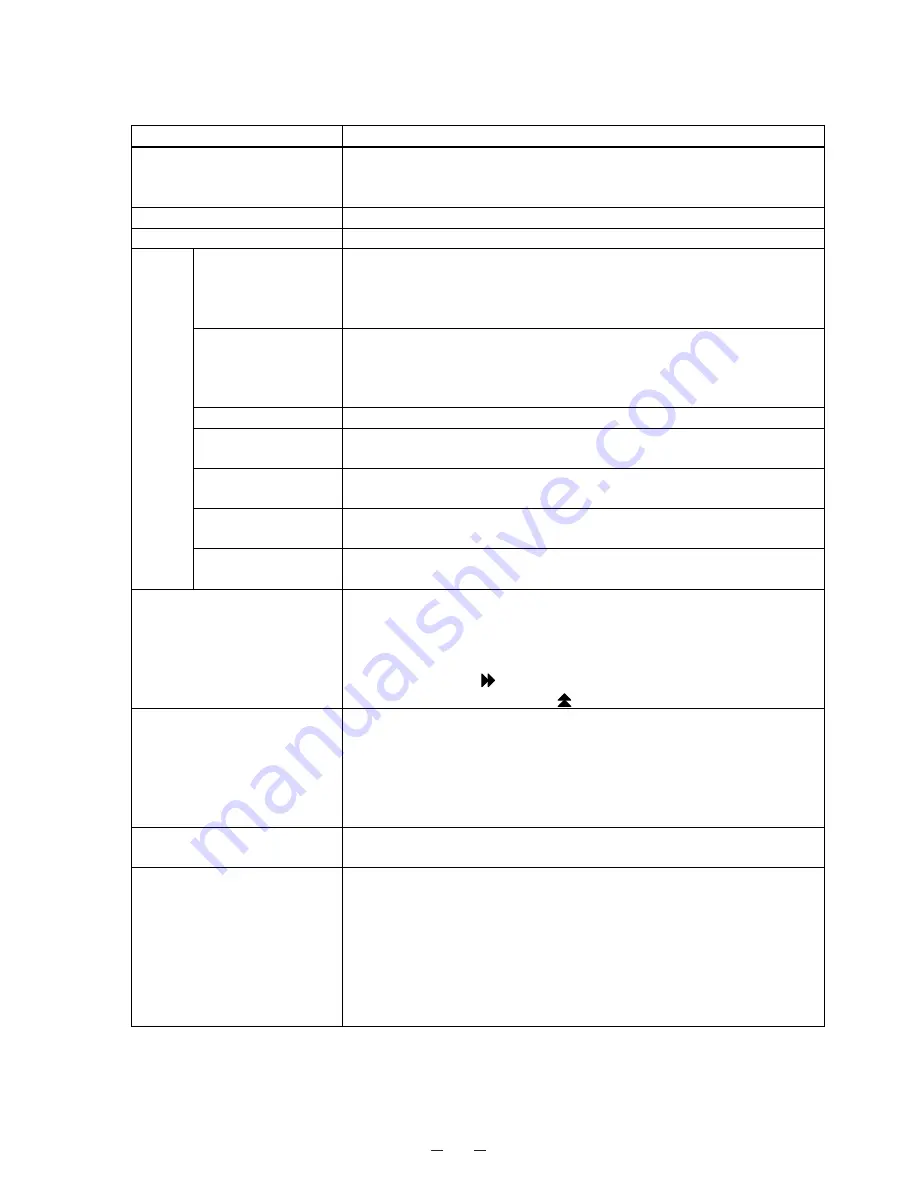
Control specifications
Item MDF-394/393(N)
Temp. controller
Microcomputer control system
Temperature setting range: -50C
㨪
-90C (Unit: 1C)
Non-volatile memory
Thermal sensor
Pt.1000
ȍ
Temperature display
LED digital display
Alarms
High temp.
+5C~+20C for High temperature alarm (Initial; +10C)
ALARM lamp blinks and buzzer sounds intermittently with 15min. delay
Remote alarm contact; Normal Open, Normal Close
Allowable contact capacity; Max. 30VDC, 2A
Low temp.
-5C~-20C for Low temperature alarm (Initial; -10C)
ALARM lamp blinks and buzzer sounds intermittently with 15min. delay
Remote alarm contact; Normal Open, Normal Close
Allowable contact capacity; Max. 30VDC, 2A
Filter check
FILTER lamp blinks and buzzer sounds intermittently
Power failure
ALARM lamp blinks, buzzer sounds intermittently and remote alarm is
output.
Remote alarm
ޔ
Remote alarm terminal 3P; DC30V 2A
NC-COM, NO-COM
Battery lifespan
‘F1’ and PV are displayed alternately when battery accumulation time is
about 3 yrs
Fan motor lifespan
‘F2’ and PV are displayed alternately when fan motor accumulation time
is about 6 yrs
Control panel
Lamps: ALARM, FILTER CHECK
Buzzer key: BUZZER
Alarm test key: ALARM TEST
Set key: SET
Digit shift key:
Numerical value shift key:
Self diagnosis
When any failure is occurred in sensor among temp. sensor, filter
sensor, cascade sensor and AT sensor;
z
Error code and chamber temperature are displayed alternately
z
ALARM lamp blinks
z
Remote alarm activates
z
Buzzer sounds intermittently
Alarm resume time
The buzzer will be activated again after certain suspension if the alarm
condition is continued. (Initial; 30 minutes)
Compressor protection
When the cascade sensor temperature is lower than -34C, L side
compressor is turned on.
When the cascade sensor temperature is higher than -18C, L side
compressor is turned off.
When the filter sensor is higher than +60C, High side compressor is
turned off.
Overload relay for L side compressor, Internal thermometer for High
side compressor
㩷
2
Summary of Contents for MDF-393
Page 7: ...4 Dimensions Over view Front view Side view ...
Page 12: ...Wiring Diagram 9 ...
Page 13: ...Circuit Diagram 10 ...


