background image


23


   MONITOR OF FREEZER STATUS 


The freezer has a function to monitor the running status of the unit as shown in table 7 below.    This is to 

notice the running status getting worse (not failure). 


1.

 The STATUS lamp is lit when one of the running status shown in table 7 is detected. 

2.

 The S code (--X, X: 1 to 3) is displayed on the temperature indicator by pressing STATUS key when 

the STATUS lamp is lit. 

3.

 Pressing the STATUS key again returns to current chamber temperature on the temperature indicator.   

(The indication returns to the chamber temperature display automatically when no key is operated for 90 

seconds.) 


Table 7.    Monitor of running status 

Kind of 

function 

Status Indication 

If this status 

continues 

Remedy 

Notice of 

abnormal 

ambient 

temperature 

When the ambient 

temp. is over approx. 

35

o

C or lower than 

about 0

o

C. 

STATUS lamp   

lights. 

“--1” is displayed. 

Decrease of cooling 

performance or 

durability of 

refrigerating circuit. 

Recheck air- 

conditioning of 

installed site. 

Notice of low 

voltage 

When the power 

source voltage is 

less than approx. 

195V when the rated 

voltage is between 

220 and 240V. 

STATUS lamp   

lights. 

“--2” is displayed. 

Abnormal heat at 

power supply outlet 

or degrade of 

starting performance 

of refrigerating 

circuit 

Use dedicated 

power source. 

Notice of 

overload 

condition 

When the running 

rate of refrigerating 

Circuit is higher than 

usual. 

STATUS lamp   

lights. 

“--3” is displayed. 

Decrease of cooling 

performance or 

durability of 

refrigerating circuit. 

1. This is likely to 

happen when a 

large amount of 

materials is stored. 

2. Check ambient 

temp., voltage, and 

sealing of 

outer/inner door. 

Note: 

• The S code displayed on the temperature indicator is changed every few seconds if two or three status 

shown in the above table are detected at the same time.   

--1 

 --2 

 --3 

 --1  repeated


• The monitoring function does not trigger a buzzer or conduct a safety operation. 

the case of multiple indication of S code, follow the remedy for each status. 

• The status monitor lamp (STATUS) may be lit under normal running condition when the independent 

inner door (MDF-7ID or MDF-5ID) is installed because of less cooling performance.    In this case, adjust 

the air conditioning so that the ambient temperature is around 23

o

C, or set the chamber temperature 

10

o

C higher than the current setting. 


Summary of Contents for MDF-U52V

Page 1: ...MDF U72V MDF U72VC MDF U52V MDF U52VC Ultra Low Temperature Freezer INSTRUCTION MANUAL MDF U72V MDF U72VC ...

Page 2: ...e expressed written permission of SANYO 2 The contents of this manual are subject to change without notice 3 Please contact SANYO if any point in this manual is unclear or if there are any inaccuracies SANYO Electric Biomedical Co Ltd All rights reserved Printed in Japan ...

Page 3: ...TING Chamber temperature P 18 Key lock function P 18 Alarm temperature setting P 19 ALARMS SAFETY FUNCTIONS P 20 SETTING OF ALARM RESUME TIME P 21 REMOTE ALARM TERMINAL P 22 MONITOR OF FREEZER STATUS P 23 CHANGE OF COMPRESSOR DELAY TIME P 24 CHANGE OF DOOR ALARM DELAY TIME P 25 ROUTINE MAINTENANCE Cleaning of cabinet P 26 Cleaning of condenser filter P 26 Defrosting of inside wall P 27 Replacement...

Page 4: ... Symbol shows this symbol means caution this symbol means an action is prohibited this symbol means an instruction must be followed Be sure to keep this manual in a place accessible to users of this unit Label on the unit This mark is labeled on the cover in which the electrical components of high voltage are enclosed to prevent the electric shock The cover should be removed by a qualified enginee...

Page 5: ...wer supply plug to the power source firmly Improper insertion may cause a heat or ignition Use a power supply outlet with ground earth to prevent electric shock If the power supply outlet is not grounded it will be necessary to install a ground by qualified engineers Never ground the unit through a gas pipe water main telephone line or lightning rod Such grounding may cause electric shock in the c...

Page 6: ...rbon dioxide gas for the back up system The CO2 density level in the air could rise and may be harmful to humans Prepare a safety check sheet when you request any repair or maintenance for the safety of service personnel Select a level and sturdy floor for installation This precaution will prevent the unit from tipping Improper installation may result in water spillage or injury from the unit tipp...

Page 7: ...nd may cause frostbite Do not lean on the door This may cause injury if the unit tips over or door is broken Put on gloves at the time of maintenance to prevent injury by the edge or corner of the components Check the filter mentioned in this manual and clean it as necessary A dusty filter may cause temperature rise or failure Do not touch the condenser directly when the filter is removed for clea...

Page 8: ... cannot complete down and frost may accumulate outside the port surroundings Always open and close the door gently Rough operation may lead fall down of stocked items incomplete closing or damage of door gasket Clean the unit with a diluted neutral dishwashing detergent Undiluted detergent can damage the plastic components For the dilution refer to the instruction of the detergent After the cleani...

Page 9: ...umidity 80 for temperature up to 31o C decreasing linearly to 50 relative humidity at 40o C 5 Mains supply voltage fluctuations not to exceed 10 of the nominal voltage 6 Other supply voltage fluctuations as stated by the manufacturer 7 Transient overvoltages according to Installation Categories Overvoltage Categories II For mains supply the minimum and normal category is II 8 Pollution degree 2 in...

Page 10: ...8 FREEZER COMPONENTS 8 1 6 2 4 12 15 inside 14 5 3 11 9 10 7 5 inside 17 18 16 13 19 ...

Page 11: ...cannot contact with the floor 10 Leveling foot The height of the freezer can be adjusted by this screw type foot Keep the unit in level at the installation 11 Fixture on back side 2 fixtures are provided as spacers between the cabinet and wall and also serve as hooks to fix the unit See page 12 Installation 12 Air intake vent grille Do not block this vent to keep the proper cooling performance 13 ...

Page 12: ...details respectively 5 Digital temperature indicator This indicator shows the present chamber temperature or set temperature 6 Alarm lamp ALARM This lamp is flashed during alarm condition 7 Alarm test key ALARM TEST To check the alarm system during freezer operation Pressing this key with the battery switch ON gets the alarm lamp to flash the remote alarm to operate and the buzzer to sound 8 Door ...

Page 13: ...may result in injury from the unit falling or tipping over Select a level and sturdy floor for installation This precaution will prevent the unit from tipping Improper installation may result in water spillage or injury from the unit tipping over Always install the unit in a stable condition to avoid the vibration or noise Unstable floor may cause the vibration or noise A location not prone to hig...

Page 14: ...els with a dry cloth 2 Adjusting the leveling foot Extend the leveling feet by rotating them counterclockwise to contact them to the floor Ensure the unit is level 3 Fixing the unit Two fixtures are attached to the rear of the frame Fix the frame to the wall with these fixtures and rope or chain 4 Ground earth WARNING Use a power supply outlet with ground earth to prevent electric shock If the pow...

Page 15: ...r screws shown by arrows on the front panel and take the panel off By removing seven screws take off the left side panel Then take off the cover for the recorder mounting space by removing four screws Fig 1 2 As shown in the Fig 2 insert the temperature recorder to the mounting space and fix it to the back side of the front panel by using the recorder fixture enclosed with the recorder 3 Take off ...

Page 16: ... the recorder sensor through it 6 Attach the recorder sensor on the sensor cover with the enclosed clips Seal the access port with a silicon and replace the recorder sensor cover Fix the cover to the inside wall Fig 6 7 Remove the connector cover Connect the recorder connector at the end of the power cord with the white connector on the left of the base compartment Bind the extra lead wire of the ...

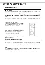
Page 17: ...em is ready To stop the operation of the system turn off this switch 2 Test switch TEST This switch is for checking the operation of back up system Pressing this switch is resulted in the release of liquid carbon dioxide without system operation 3 Temperature setting knob TEMP SET With this knob set the temperature at which the system is operated The effective set temperature range is between 50o ...

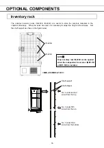
Page 18: ... necessary to adjust the height of the shelves Set the shelf support as shown in the figure below Shelf support Shelf stopper No 4 under second screw from the top No 3 under fifth screw from the top No 3 under third screw from the bottom IR 220U IR 224U MDF U72V MDF U72VC NOTE Only inventory rack IR 220U can be applied when the independent inner door MDF 7ID or MDF 5ID is installed ...

Page 19: ...ZER to silence the alarm 5 Set the desired chamber temperature See page 18 for the temperature setting 6 Check that the chamber temperature reaches the desired temperature 7 Turn on the switch of the back up system optional component if it is installed 8 Make sure that the alarm lamp blinks and the buzzer sounds by pressing the alarm test key ALARM TEST 9 After confirming the above you can put art...

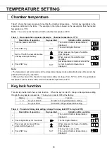
Page 20: ...ode returns to the temperature display mode automatically when 90 seconds has passed without any key operation Although the value of the chamber temperature setting can range from 50o C to 90o C the guaranteed temperature with no load is 85o C when the ambient temperature is 30o C Key lock function This unit is provided with the key lock function When the key lock is ON change of temperature setti...

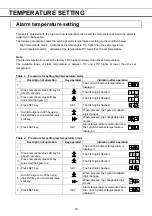
Page 21: ...irst digit is flashed 3 Press numerical value shift key and scroll the figure to 1 The first digit is flashed 4 Press SET key SET The first digit is flashed When pressed the figure of settable digit changes 5 Scroll the figure to 005 by using digit shift key and numerical value shift key When pressed the changeable digit moves 6 Press SET key SET Alarm temperature is memorized and the current cham...

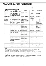
Page 22: ...cade sensor is disconnected ALARM lamp is flashed E03 and chamber temp are displayed alternately Intermittent tone Remote alarm If the cascade sensor is short circuited ALARM lamp is flashed E04 and chamber temp are displayed alternately Intermittent tone Remote alarm If the filter sensor is disconnected ALARM lamp is flashed E05 and chamber temp are displayed alternately Intermittent tone Remote ...

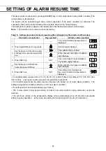
Page 23: ... numerical value shift key When pressed the figure of settable digit changes 4 Press SET key SET The current reset time is displayed The middle digit is flashed 5 Set the figure to 020 with the numerical value shift key When pressed the figure of settable digit changes 6 Press SET key SET The setting is memorized and the current chamber temperature is displayed The settable alarm resume time is 10...

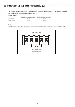
Page 24: ...alarm is outputted from this terminal Contact capacity is DC 30V 2 A Contact output between COM and N O between COM and N C At normal Open Close At abnormal Close Open Note The alarm is actuated when the power cord is disconnected from the outlet or the power switch is OFF REMOTE ALARM N C COM N O MAX DC30V 2A ...

Page 25: ...han approx 195V when the rated voltage is between 220 and 240V STATUS lamp lights 2 is displayed Abnormal heat at power supply outlet or degrade of starting performance of refrigerating circuit Use dedicated power source Notice of overload condition When the running rate of refrigerating Circuit is higher than usual STATUS lamp lights 3 is displayed Decrease of cooling performance or durability of...

Page 26: ... for delay time change from 2 minutes to 4 minutes Description of operation Key operated Indication after operation 1 The current chamber temperature is displayed 2 Press numerical value shift key for 5 seconds The first digit is flashed 3 Set the figure to F05 with the numerical value shift key When pressed the figure of settable digit changes 4 Press SET key SET The current delay time is display...

Page 27: ... of operation Key operated Indication after operation 1 The current chamber temperature is displayed 2 Press numerical value shift key for 5 seconds The first digit is flashed 3 Set the figure to F04 with the numerical value shift key When pressed the figure of settable digit changes 4 Press SET key SET The current delay time is displayed The first digit is flashed 5 Set the figure to 003 with the...

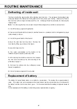
Page 28: ...er pour water onto or into the unit Doing so can damage the electric insulation and cause failure The compressor and other mechanical parts are completely sealed This unit requires absolutely no lubrication Check the back up system by pressing TEST switch once a month if it is installed Remove the frost or ice on the chamber wall and clean the condenser filter once a month Cleaning of condenser fi...

Page 29: ...4 Open the outer door and inner door Remove the inner door by lifting up as shown in the figure 5 Leave the freezer as it is 6 The water accumulated on the bottom of the chamber should be wiped up with a dry cloth 7 After cleaning the chamber and inner door replace the inner door and start up the unit according to the procedure on page 17 8 Put back the articles into the sufficiently cooled freeze...

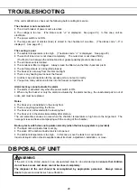
Page 30: ...mpartment Alarm test key cannot actuate the alarm The alarm is activated only when the power switch is ON When only the buzzer or only the alarm is actuated by the alarm test key the unactuated part is out of order and must be replaced Noise The freezer is not installed on the sturdy floor There is anything touching the frame The freezer is not leveled with the leveling feet The freezer is in the ...

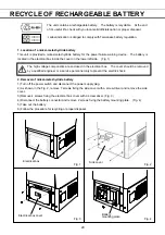
Page 31: ...nents are enclosed in the electrical box The cover should be removed by a qualified engineer or a service personnel only to prevent the electric shock 2 Removal of nickel metal hydride battery 1 Turn off the power switch and disconnect the power supply plug 2 As shown in the Fig 2 remove 7 screws fixing the side cover with a screw driver and remove the side cover 3 Remove 4 screws fixing the elect...

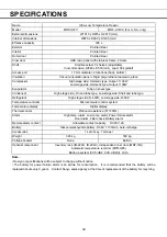
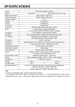
Page 32: ... type Refrigerant High stage side R 407D Low stage side R 508 Temperature controller Microcomputer control system Temperature display Digital display Thermal sensor Platinum resistance Pt 1000Ω Alarm High temp alarm Low temp alarm Power failure alarm Door alarm Filter check Battery alarm Remote alarm contact Allowable contact capacity DC 30V 2A Battery Nickel metal hydride battery DC6V 1100mAh Aut...

Page 33: ...type Refrigerant High stage side R 407D Low stage side R 508 Temperature controller Microcomputer control system Temperature display Digital display Thermal sensor Platinum resistance Pt 1000Ω Alarm High temp alarm Low temp alarm Power failure alarm Door alarm Filter check Battery alarm Remote alarm contact Allowable contact capacity DC 30V 2A Battery Nickel metal hydride battery DC6V 1100mAh Auto...

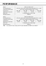
Page 34: ... level 51 dB A background noise 20 dB Maximum pressure 3085 kPa Model MDF U52V MDF U52VC Cooling performance 86o C at the center of the chamber ambient temperature 30o C no load Temperature control range 50o C to 86o C ambient temperature 30o C no load Power source 220V 50Hz 220V 60Hz 230V 50Hz 240V 50Hz Rated power consumption 1025 W 1505 W 1045 W 1090 W Noise level 51 dB A background noise 20 dB...

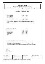
Page 35: ...ior No contamination Decontaminated Contaminated Others 3 Instructions for safe repair maintenance of the unit a The unit is safe to work on b There is some danger see below Procedure to be adhered to in order to reduce safety risk indicated in b below Date Signature Address Division Telephone Product name Model Serial number Date of installation Ultra low temperature MDF U72V U72VC freezer MDF U5...

Page 36: ...7FB6P101356005 5 April 2005 Recycled paper SANYO Electric Biomedical Co Ltd 10 15 Hongo 3 Chome Bunkyoku Tokyo 113 8434 Japan Printed in Japan ...

Reviews: