background image

INSTRUCTION MANUAL

MPX-CD4P
MPX-MD4P

Multiplexer

English

GB 

Multiplexer

Deutsch

Multiplexeur

Français

Multiplexor

Español

Multi distributore

Italiano


About this manual

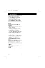
Before installing and using this unit, please read this manual
carefully. Be sure to keep it handy for later reference.

This manual gives basic connections and operating
instructions for 2 models (Colour MPX-CD4P, B/W
MPX-MD4P).

Über diese Anleitung

Lesen Sie bitte diese Bedienungsanleitung vor der
Installation und der Verwendung des Gerätes sorgfältig
durch. Bewahren Sie die Anleitung zum späteren
Nachschlagen auf.

In dieser Anleitung werden die Anschlüsse und die
Bedienungsanleitungen für 2 Modelle (Farbe MPX-CD4P,
Schwarzweiß MPX-MD4P) beschrieben.

À propos de ce manuel

Avant d’installer et d’utiliser cet appareil, veuillez lire ce
manuel attentivement. Assurez-vous de le garder à portée de
la main pour référence ultérieure.

Ce manuel couvre les instructions de branchement et
d’utilisation de base pour deux modèles (couleur MPX-CD4P,
noir et blanc MPX-MD4P).

Acerca de este manual

Antes de instalar y usar este aparato, lea detenidamente este
manual. Asegúrese de guardarlo a mano para futuras
referencias.

Este manual le indica las conexiones básicas y las
instrucciones de funcionamiento de dos modelos (Color
MPX-CD4P, Blanco y negro MPX-MD4P).

Nota su questo manuale

Leggere attentamente questo manuale prima di passare
all’installazione ed all’uso di questo apparecchio.

Questo manuale contiene istruzioni per i principali
collegamenti ed il funzionamento di due modelli (il modello a
colori MPX-CD4P, ed il modello in bianco e nero MPX-MD4P).

L8FH5/XE (MPX-CD4P, MD4P GB) 1999. 12. 2

Summary of Contents for MPX-CD4P

Page 1: ...À propos de ce manuel Avant d installer et d utiliser cet appareil veuillez lire ce manuel attentivement Assurez vous de le garder à portée de la main pour référence ultérieure Ce manuel couvre les instructions de branchement et d utilisation de base pour deux modèles couleur MPX CD4P noir et blanc MPX MD4P Acerca de este manual Antes de instalar y usar este aparato lea detenidamente este manual A...

Page 2: ... to strong vibrations Avoid moving the multiplexer between cold and hot locations Do not place the multiplexer directly on top of a monitor TV as this may cause playback or recording problems Avoiding Electrical Shock and Fire Do not handle the power cord with wet hands Do not pull on the power cord when disconnecting it from an AC wall outlet Grasp it by the plug If any liquid is spilled on the m...

Page 3: ...NTROL SETTING 31 ALARM DATA DISPLAY 33 ALARMS OPERATIONS 34 EXTERNAL ALARMS 34 VIDEO LOSS ALARM 34 RS232C CONTROL 35 CONNECTION 35 INTERFACE SPECIFICATIONS 35 COMMANDS 35 SPECIFICATIONS 39 FEATURES Duplexing function that allows 4 divisions split screen display even during live picture recording High speed single field switching Normal live picture display in 4 divisions split screen Video sensor ...

Page 4: ... full screen display modes press this button for a 2x zoomed in image Press the button one more time to cancel 6 SEQUENCE button and indicator In 4 divisions split screen or full screen display modes press this button for an automatic sequential full screen display of the pictures 7 QUAD button and indicator In full screen display or sequential display modes press this button to switch to 4 divisi...

Page 5: ... attach the power cord to the holder as illustrated I AC Power socket Insert the power cord female plug firmly into this socket When the other plug of the power cord is connect to a live power source the POWER indicator on the front panel will light NOTE Model MPX MD4P does not have S VIDEO IN OUT terminals RS232C terminal Pin No Signal Function Signal direction 1 2 RXD Data reception Computer Mul...

Page 6: ...VCR MONITOR 1 CONTROL G C R1R2 C S C A C 1 2 3 4 C 1 2 3 4 External alarm sensors door bell interphone etc Monitors sold separately Video input terminal Video input terminal Video output terminal Video input terminal Timelapse VCR sold separately Alarm input terminal Switching output terminal Computer VIDEO IN VIDEO OUT CAMERA IN Signal flow See page 35 VCR MONITOR COM COM COM IN 1 2 OUT IN OUT S ...

Page 7: ...lign the slot on the mounting bracket with the two bolts Make sure the bolts have not moved from their position then place a flat washer a locking washer and fix with a nut NOTE Make sure to use the bolts provided with this unit as the bolts provided with the rack mount hardware are too short 3 Install the second mounting bracket on the opposite side then attach the unit onto the rack using the ra...

Page 8: ...age will be displayed on monitor 1 when the VCR button is pressed While in VCR playback mode you can use the still and zoom functions see page 15 NOTE If playing back a tape not recorded through this unit NO ID will be displayed on the monitor screen Menu Mode Press the MENU button to display the menu The buttons used for menu control see page 21 are indicated below Menu control buttons 1 c l VCR ...

Page 9: ...e If the power is turned off for about one hour or more when the power is restored the CLOCK SET menu is displayed so the clock settings can be checked If the clock settings are reset to 01 01 2000 SAT 00 00 00 that may indicate that the battery is dead and must be replaced Replacing the Battery To replace the battery please consult your dealer After the battery has been replaced press the ALL RES...

Page 10: ...SET on page 31 for more information on settings for recording MONITOR 1 DISPLAYS AND FUNCTIONS MONITOR 2 DISPLAYS AND FUNCTIONS LIVE LIVE Monitor 1 4 divisions split screen Still image STILL 4 P10 Zoomed in image ZOOM 4 P10 Automatic sequential display SEQUENCE P14 Full screen 1 P12 Still image Zoomed in image STILL ZOOM Zoomed in still image STILL STILL 0 1 s z z sz sz ZOOM 4 P11 4 Zoomed in stil...

Page 11: ...e Press the camera select 4 button one more time then press the STILL button The camera 4 indicator and the STILL indicator go off Example 2 To zoom in the image from camera 4 1 Press the ZOOM button The ZOOM indicator flashes and the zoomed in image display mode is selected 2 Press the camera select 4 button The camera 4 indicator flashes the image from camera 4 is zoomed in and Z flashes on scre...

Page 12: ...ted by the zoom range frame is now zoomed in If necessary follow the same procedure to set the zoom range for the other cameras NOTE You can switch from zoomed in mode to normal no zoom mode by pressing the camera select 4 button repeatedly To cancel the zoomed in image display mode Press the ZOOM button Example 4 To freeze the zoomed in image from camera 4 1 Press the ZOOM button The ZOOM indicat...

Page 13: ...age display mode Press the STILL button S is erased and the normal display mode returns Example 6 To zoom in the image from camera 3 1 Press the camera select 3 button The camera 3 indicator lights the image from camera 3 is displayed 2 Press the ZOOM button The ZOOM indicator flashes the image from camera 3 is zoomed in and Z flashes on screen NOTE The zoomed in area will be as set by the zoom ra...

Page 14: ...y the zoom range frame is now zoomed in If necessary follow the same procedure to set the zoom range for the other cameras To cancel the zoomed in image display mode Press the ZOOM button Z is erased and the normal display mode returns While in zoom mode if the camera select button is pressed one more time depending on the movement of the subject the image may be more or less clear Pressing the ca...

Page 15: ...ized and the last one previously used will be automatically selected A SEQUENTIAL DISPLAY MODE OPERATIONS Press the camera select 2 button The camera 2 indicator lights the picture from camera 2 is displayed on monitor 2 B FULL SCREEN DISPLAY MODE OPERATIONS Press the SEQUENCE button The SEQUENCE indicator lights sequential display mode is selected To cancel the monitor 2 operations Press the MON2...

Page 16: ...1 a live picture will be displayed on monitor 2 VCR LIVE Monitor 1 4 divisions split screen Still image STILL 4 P16 Zoomed in image ZOOM 4 P16 Automatic sequential display SEQUENCE P20 Full screen 1 P18 Still image Zoomed in image STILL ZOOM Zoomed in still image STILL STILL 0 1 s z z sz sz ZOOM 4 P17 4 Zoomed in still image Zoom range setting Zoom P18 P18 QUAD VCR 4 divisions split screen Monitor...

Page 17: ...e Press the camera select 4 button one more time then press the STILL button The camera 4 indicator and the STILL indicator go off Example 2 To zoom in the recorded image from camera 4 1 Press the ZOOM button The ZOOM indicator flashes and the zoomed in image display mode is selected 2 Press the camera select 4 button The camera 4 indicator flashes the recorded image from camera 4 is zoomed in and...

Page 18: ...by the zoom range frame is now zoomed in If necessary follow the same procedure to set the zoom range for the other cameras NOTE You can switch from zoomed in mode to normal no zoom mode by pressing the camera select 4 button repeatedly To cancel the zoomed in image display mode Press the ZOOM button Example 4 To freeze the zoomed recorded in image from camera 4 1 Press the ZOOM button The ZOOM in...

Page 19: ...image display mode Press the STILL button S is erased and the normal display mode returns Example 6 To zoom in the recorded image from camera 3 1 Press the camera select 3 button The camera 3 indicator lights the recorded image from camera 3 is displayed 2 Press the ZOOM button The ZOOM indicator flashes the recorded image from camera 3 is zoomed in and Z flashes on screen NOTE The zoomed in area ...

Page 20: ... seconds the display mode will automatically return to zoomed in display mode To return to the setting mode press the camera select 4 button again for about 3 seconds 4 Press the c or l button to move the zoom range frame to the desired area of the image 5 Press the camera select 4 button The area selected by the zoom range frame is now zoomed in If necessary follow the same procedure to set the z...

Page 21: ...al The camera select indicators 1 4 light sequentially according to the displayed camera NOTE The sequential display speed image interval is set to 1 second in the MONITOR SET menu To change the sequence speed setting refer to MON1 SEQ TIMER on page 30 Only the channels where a camera image was recorded will be displayed Empty channels will be skipped automatically SEQUENCE L8FH5 XE MPX CD4P MD4P ...

Page 22: ...RA3 ON ON CAMERA4 ON ON DISPLAY SET LIVE CLOCK OFF TITLE ON VCR PB CLOCK OFF TITLE ON POSITION SET PRESS NEXT MONITOR SET MON1 SEQ TIMER 01 S MON2 SEQ TIMER 01 S MON2 MON1 N VCR SET VCR MODE TLS REC SPEED 003 H ALARM REC SPEED 003 H VIDEO LOSS SET VIDEO LOSS ON DATA ON DISPLAY FREEZE RS232C SET DATA SPEED 19200 ALARM DATA 1 13 CAM DATE TIME ITEM 1 2 3 4 5 6 7 8 MENU MENU LANGUAGE LANG SPRACHE ENGL...

Page 23: ...n to go to the next menu or Press the EXIT button to exit the menu display and the selected language is set All the on screen menus and settings will be displayed in the selected language LIVE MENU LANGUAGE LANG SPRACHE ENGLISH FRANCAIS DEUTSCH HORLOGE 01 01 2000 SAM 00 00 00 HEURE ETE MODE NON SEM MOIS HEURE MAR DER DIM 03 02 00 ARR DER DIM 10 02 00 UHRZEIT 01 01 2000 SA 00 00 00 SOMMERZEIT EINST...

Page 24: ...ast Sunday of October at 2 00 AM LST SUN 10 02 00 TO MAKE CHANGES TO THE SETTINGS 1 Press the l button to highlight the NO USE setting then press the or button to select USE and press the l button one more time 2 Example Setting the summer time from the second Tuesday of May at 3 00 AM to the fourth Tuesday of September at 3 00 AM 1 Press the or button to set the WEEK 2ND then press the c button M...

Page 25: ... A B C X Y Z Numbers 0 1 8 9 Symbols _ 2 Following the same procedure enter the rest of the title ATE 1F 3 Press the l button to set the cursor at the first character location for camera 2 Press the or button to set first character H then press the c button 4 Following the same procedure enter the rest of the title ALL 2F 3 Press the MENU button to go to the next menu screen or Press the EXIT butt...

Page 26: ...etting If FULL is selected refer to STILL ZOOM and DOUBLE ALARM below for further settings QUAD If an alarm trigger is received while in full screen the display mode will switch to 4 divisions split screen If QUAD is selected refer to STILL and ZOOM below for further settings NC The display mode will remain unchanged when an alarm trigger is received STILL ON The image from the camera correspondin...

Page 27: ...VITY LEVEL Example To adjust the camera 2 sensor position and sensitivity level to 3 1 From the SENSOR SET menu press the NEXT button twice to go to the sub menu for camera 2 The sub menu for each camera is selected by pressing the NEXT button The camera live picture is displayed and the sensor position and sensitivity can be adjusted for that camera 2 Using the l or c button move the sensor frame...

Page 28: ...ut ACTIVE REC OFF ACTIVE REC MODE1 ACTIVE REC MODE2 Alarm trigger in Alarm trigger in Alarm trigger in Alarm trigger out Alarm trigger out Alarm trigger in Alarm duration for camera 2 Alarm trigger received from camera 4 during the alarm duration for trigger from camera 2 Normal recording no alarm trigger Alarm trigger out Alarm trigger out Alarm duration for camera 2 is over remaining alarm durat...

Page 29: ...ess the l button to switch to the CAMERA 2 setting and repeat the setting procedure above Following the same procedure as above select the CAMERA 3 and 4 settings 4 Press the MENU button to go to the next menu screen or Press the EXIT button to exit the menu display NOTE The OFF and ON settings made in this menu will not affect the display of the camera signals on the monitor They only set when th...

Page 30: ...ck is not displayed during VCR playback picture mode Default setting VCR PB TITLE ON The camera title is displayed during VCR playback picture mode Default setting OFF The camera title is not displayed during VCR playback picture mode SETTING THE CAMERA TITLE AND THE CLOCK DISPLAY POSITION POSITION SET 1 From the DISPLAY SET menu press the NEXT button The 4 divisions split screen display mode is s...

Page 31: ...ON1 SEQ TIMER To set the display sequence speed interval on monitor 1 The available intervals are 01 Default setting 02 03 04 05 10 20 30 seconds MON2 SEQ TIMER To set the display sequence speed interval on monitor 2 The available intervals are 01 Default setting 02 03 04 05 10 20 30 seconds MON2 MON1 To have monitor 1 display the same image as monitor 2 N No Monitor 2 will only display camera liv...

Page 32: ...se VCR The available speeds are 003 3H Default setting 012 12H 024 24H NC F3 NC When an alarm trigger is received the recording speed is not changed and stays as set under REC SPEED F3 Use this setting when using the SW output terminal on a timelapse VCR that does not output a switching signal in 3H mode With a real time VCR Set the recording speed to use when an alarm trigger is received to match...

Page 33: ...osses to be recorded as alarm data To view the recorded data refer to ALARM DATA DISPLAY on page 33 ON The video losses data is recorded as alarm data Default setting OFF The video losses data is not recorded DISPLAY You can set the display mode when there is an interruption in the video signal feed FREEZE When there is video loss the image just previous to the interruption is frozen on screen Def...

Page 34: ...isplay the menu display The codes in the ITEM column indicate the type of alarm data E External alarm trigger see page 25 V Video loss see page 32 S Sensor alarm see page 26 NOTE When the number of recorded alarm data entries reaches 100 the oldest ones are erased as new ones are recorded The alarm data screens are only displayed when alarm data entries are recorded ALARM DATA 1 13 CAM DATE TIME I...

Page 35: ...ing to the settings entered in the MONITOR SET menu During normal monitoring operations the camera select indicator lights according to the displayed camera If there is an alarm trigger for another camera the indicator will flash VIDEO LOSS ALARM If there is an interruption of the video signal the buzzer is heard and the image just previous to the interruption is frozen on screen or color bars are...

Page 36: ...cture from a camera to be displayed full screen on monitor 1 QUAD 83 To display a 4 divisions split screen on monitor 1 SEQUENCE 87 To switch the display mode from full screen to sequential display on monitor 1 ZOOM 85 To zoom in the picture on monitor 1 STILL 86 To freeze the picture on monitor 1 LIVE 80 To select the live input mode VCR 81 To select the VCR playback input mode MON2 88 To set the...

Page 37: ...ication SENSOR is ON 4 Reserved 0 3 Monitor 1 display state mode indication 0000 Normal display mode 2 0001 Sequential display mode 1 0010 Zoomed in mode 0 0011 Still image mode 0100 Frozen zoomed in image 0101 Zoomed in still image 0110 Zoom range setting mode 0111 Zoomed in still image range setting mode Third byte Bit Bit state information 7 Reserved 6 Reserved 5 Monitor 2 operation MON2 setup ...

Page 38: ...ansmission see Table 3 ALARM information Table 3 Bit Bit state information 7 Alarm information indication 01 External 6 10 Video loss 11 Sensor alarm 5 Reserved 0 4 Reserved 0 3 Camera number indication 0011 CAMERA NO 4 2 0010 CAMERA NO 3 1 0001 CAMERA NO 2 0 0000 CAMERA NO 1 OTHER COMMANDS ENTER 40 When numeric commands are all sent this command is used to enter the transmitted value CLEAR 56 To ...

Page 39: ... 0 0 ENTER LIVE FULL 1 1 1 VCR PB FULL 2 2 2 VERSION MULTI FULL 3 3 3 SHIFT QUAD FULL 4 4 4 1 O MENU PLUS 5 5 NEXT ZOOM 6 6 CLEAR EXIT STILL 7 7 SEQ 8 8 MON 2 9 9 SECURITY LOCK ON A ACK SECURITY LOCK OFF B NAK POWER ON OFF C SET ON D SET OFF E F A B C D E F 0 CLK ADJ 1 MENU RESET 2 3 4 5 ALARM STATUS SENSE 6 7 STATUS SENSE 8 9 A B C D E F ALARM L8FH5 XE MPX CD4P MD4P GB 1999 12 2 38 English ...

Page 40: ...u to display the same image as monitor 1 Control terminal CONTROL Alarm input 1 4 No voltage make contact switch input x 4 Low input Remote input R1 R2 2 wire type with resistance based identification system Alarm output A DC 5V 5 7kΩ Low output Switching input S Low input for input signal from SW OUT of timelapse VCR real time recorder as per this manufacturer specifications RS 232C terminal 9 pi...

Page 41: ...SANYO Electric Co Ltd 1AC6P1P1911 L8FH5 XE 0499KP NI01 Printed in Japan L8FH5 XE MPX CD4P MD4P GB 1999 12 2 ...

Reviews: