21
Installation
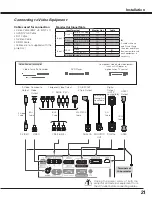
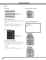
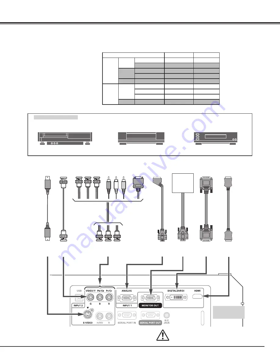
Connecting to Video Equipment
Video Source (example)
Video Cassette Recorder
DVD Player
RGB SCART
21-pin Output
Y Pb/Cb Pr/Cr
Y-Pb/Cb-Pr/Cr
Component video output equipment.
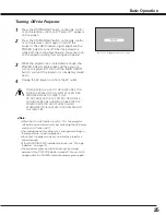
(such as DVD player or
high-definition TV source.)
Component Video Output
BNC
Cable
DVI
Cable
SCART-VGA
Cable
DIGITAL
Unplug the power cords of both the
projector and external equipment from
the AC outlet before connecting cables.
S-Video
Output
S-VIDEO
Cables used for connection
• Video Cable (BNC x 3, BNC x 1)
• SCART-VGA Cable
• DVI Cable
• S-Video Cable
• HDMI Cable
( Cables are not supplied with the
projector.)
Composite
Video
Output
S-Video
Cable
VIDEO
ANALOG
Terminals of
the projector
BNC
Cable
Digital
Output
(HDCP
compatible)
HDMI
Output
HDMI
Cable
HDMI
Input Terminal
Monitor Out
Cable
Input 1
D-sub15
RGB (PC analog)
YES
RGB (SCART)
NO
DVI-D
RGB (PC digital)
NO
RGB (AV HDCP)
NO
HDMI
HDMI
NO
Input 2
5BNC
RGB
YES
Video
YES
Q
Y-Pb/Cb-Pr/Cr
YES
Q
S-video S-video
NO
Monitor Out Signal Table
Q
A cable with one
end D-sub 15 and
the other end (Black
box) compatible with
each equipment is
necessary.
MONITOR
OUT
Refer to the
Monitor Out
Signal Table
(above).


