K8E
1
4
K66A
1
3
K66B
1
3
K66C
1
3
K66D
1
3
K66E
1
3
K8H
1
6
1
3
A10B30900
SP1
K66F
1
3
M10B23004
FN906
M10B28900
FN902
M10B28800
FN901
M10B26502
FN903
M10B28900
FN905
M10B22406
FN904
6.3KZ
47ME
C2813
6.3KZ
47ME
C2814
10KZ
1UGQFZ
C2811
KK470
GQBY
C2812
J10EG040G
K68C
1
4
5V
02DZ
6.2YG
D2812
02DZ6.2YG
D2811
1/16GJ
47C
R2811
1/16GJ
100C
R2812
U22B0030G
A2811
1
VCC
2
VOUT
3
GND
1
SDA
2
SCLK
3
D.S.
4
GND
5
INT OUT
6
A1
7
A0
8
+VS
25KZ
0.1GQFZ
C8823
CJ33CGQY
C8822
CJ33CGQY
C8821
5V
J10EG060G
K88A
1
6
1/16GJ
10KC
R8823
1/16GJ10C
R8821
1/16GJ10C
R8822
1/16GJ100C
R8831
K8G
1
15
READY
(GREEN)
SML-310LTMG
D2862
WARNING
TEMP.
(RED)
25KZ0.1
GQF
C2861
16KK10BB
C2862
AH
Q2861
AH
Q2862
AH
Q2863
AJ
Q2864
S10B3530G
SW6808
POWER
S10B3530G
SW6804
SELECT
S10B3530G
SW6801
INPUT
S10B3530G
P-UP
SW6809
S10B3530G
P-DOWN
SW6806
S10B3530G
MENU
SW6802
S10B3530G
P-LEFT
SW6811
S10B3530G
P-RIGHT
SW6807
1SS355
D6802
1SS355
D6803
5V
02DZ6.2YG
D2867
02DZ6.2YG
D2869
02DZ6.2YG
D2868
02DZ6.2YG
D2866
02DZ6.2YG
D2871
02DZ6.2YG
D2872
SML-310YTMG
;SML-310YTLG
;SML-310YTKG
D2861
LAMP
REPLACE
(YELLOW)
02DZ6.2YG
D6807
02DZ6.2YG
D6806
SML-521MUWG
D2863
POWER
(RED)
1
2
RED
3
4
GREEN
J10EZ150G
K68B
1
15
02DZ
6.2YG
D6809
02DZ
6.2YG
D6811
02DZ6.2YG
D6808
KZ0.01GQFZ
C2863
KZ0.01
GQFZ
C2864
KZ0.01
GQFZ
C2866
KZ0.01
GQFZ
C2867
KZ0.01
GQFZ
C2868
KZ0.01
GQFZ
C2869
1SS355
D6801
02DZ6.2YG
D6804
1/16GJ47C
R6802
1/16GJ1KC
R2862
1/16GJ
4.7KC
R2864
1/16GJ
4.7KC
R2868
1/16GJ1KC
R2866
1/16GJ680C
R2872
1/16GJ
4.7KC
R2874
1/16GJ
1KC
R2876
1/16GJ
4.7KC
R2891
1/16GJ
1KC
R2878
1/16GJ390C
R2869
1/16GJ47C
R6803
1/16GJ47C
R6801
K50A
K10D
K50B
K10E
9
10
11
12
13
14
15
16
A
B
C
D
E
F
G
H
I
J
K
R/C
LM76CHMX-5
IC8821
SENSOR
A/V
CONTROL
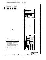
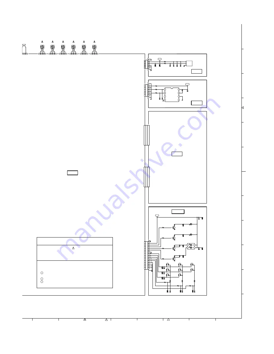
CAUTION
Fuse of the specified parts number must be used.
Unauthorized substitutions may result in fire or accident.
Components indicated by a mark in this schematic diagram designate
components in which safety can be of special significance
.
It is, therefore,
particularly recommended that the replacement of these parts must be
made by exactly the same parts
.
This projector is isolated from AC line by using the internal converter
transformer.
Please pay attention to the following notes in servicing.
1 Do not touch the part on hot side (primary circuit) or both parts on
hot and cold sides (secondary circuit) at the same time.
2 Do not shorten the circuit between hot and cold sides.
3 The grounding lead must be connected to the ground of the same
circuit when measuring of voltages and waveforms.
CAUTION
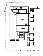
MAIN
EAKER
INTAKE FAN
INTAKE FAN
INTAKE FAN
EXHAUST FAN
EXHAUST FAN
INTAKE FAN
TEMP. SENSOR FOR OUTER
SP+
N/C
SP
-
GND
FAN_ID
FAN1
GND
FAN_ID
FAN1
GND
FAN_ID
FAN2
GND
FAN_ID
FAN2
GND
FAN_ID
FAN3
GND
FAN_ID
FAN3
5V
R/C
GND
GND
5V
GND
P_SDA1
GND
P_SCLK1
GND
5V
LAMP_LED
TEMP_LED
READY_LED
PWR_LED
GND
K11
K12
K13
K01
K02
K03
K14
K15
GND
L
A3
Schematic Diagrams
Overview
-2-
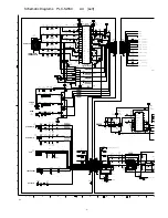
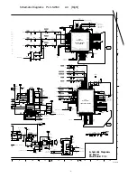
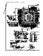
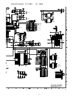
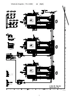
Schematic Diagrams PLC-SW30 A3 [Right]


