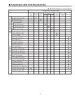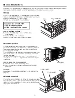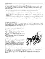
-19-
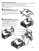
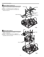
[Before Adjustment]
- Input a 100% of black raster signal.
[R/G/B-CONTRAST ADJUSTMENT]
1
Loosen a screw
A
(
Fig.1-1/1-2
) on the polarized glass mounting
base which you intend to adjust.
2
Turn the polarized glass mounting base as shown in
Fig.1-1
to
obtain the darkest brightness on the screen.
3
Tighten the screw
A
to fix the polarized glass mounting base.
Repeat steps 1 to 3 for remaining polarized glasses.
B-Polarized Glass
Mounting Base
R-Polarized Glass
Mounting Base
G-Polarized Glass
Mounting Base
A
A
A
Fig.1-
2
Fig.1-
1
Polarized
glass
mounting base
■
Optical Adjustments
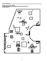
Main Board
A
Contrast adjustment
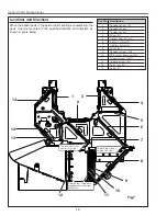
Before taking optical adjustments below, remove the Cabinet Top and Main Board following to the “Mechanical
Disassemblies”
Adjustments require a 2.0mm hex wrench and a slot screwdriver.
Note: Do not disconnect connectors K8L, K8X, K8D, K8G and K8E on the main board, because the projector can
not turn on due to operate the power failure protection.
Summary of Contents for PLC-XP40
Page 50: ... 50 CXA2101AQ RGB Matrix IC4101 IC Block Diagrams BH3540 Volume Control IC1652 ...
Page 54: ... 54 LB1645 Motor Drive IC1601 LC863316 SUB CPU IC1851 IC Block Diagrams ...
Page 55: ... 55 ML60851 USB I F IC9801 M62393 D A IC212 IC2381 IC Block Diagrams ...
Page 56: ... 56 M62399 D A IC3501 IC3551 IC Block Diagrams PW365 System Control Scan Converter IC301 ...
Page 57: ... 57 STR Z2156 Power Switching IC651 IC Block Diagrams SII161ACT DVI I F IC8001 ...
Page 58: ... 58 TA1287 RGB YUV Converter IC4551 TB1274AF Video Decoder IC1101 IC Block Diagrams ...
Page 59: ... 59 IC Block Diagrams TDA7056 Audio Output IC1631 IC1632 ...
Page 88: ...MA8 XP4500 MB8 XP4000 Mechanical Parts List 88 51 a 51 42 42 51 b 21 a 21 b 21 ...
Page 92: ... MA8A Oct 2001 2000 Printed in Japan SANYO Electric Co Ltd ...

