-24-
Electrical Adjustments
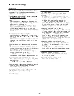
1. Receive the 16-step gray scale computer signal with
Input 1 [COMPUTER]
mode.
2. Enter the service mode.
3. Connect an oscilloscope to test point “
TP531
” (+) and
chassis ground (-).
4. Select group no. “
5
”, item no. “
16
” and change data
value to adjust the pedestal level and black level to be
the same level.
5. Connect an oscilloscope to test point “
TP501
” (+) and
chassis ground (-).
6. Select item no. “
15
” and change data value to adjust
the pedestal level and black level to be the same
level.
7. Connect an oscilloscope to test point “
TP561
” (+) and
chassis ground (-).
8. Select item no. “
17
” and change data value to adjust
the pedestal level and black level to be the same
level.
Pedestal Lebel = Black Lebel
PC Pedestal adjustment
1. Receive the a6-step gray scale computer signal with
Input 1 [COMPUTER]
mode.
2. Enter the service mode.
3. Connect an oscilloscope to test point “
2551
” (+) and
chassis ground (-).
4. Select group no. “
5
”, item no. “
6
” and change data
value to adjust amplitude “a” to be
3.8
±0.1V.
5. Select item no. “
8
” and change data value to adjust
amplitude “b” to be
3.1
±0.1V.
(a)
(b)
PSIG adjustment
1. Receive the 16-step gray scale computer signal with
Input 1 [COMPUTER]
mode.
2. Enter the service mode.
3. Connect an oscilloscope to test point “
TP531
” (+)
and chassis ground (-).
4. Select group no. “
5
”, item no. “
4
” and change data
value to adjust amplitude “a” to be
10.0
±0.1V.
5. Connect an oscilloscope to test point “
TP501
” (+)
and chassis ground (-).
6. Select item no. “
3
” and change data value to adjust
amplitude “a” to be
10.0
±0.1V.
7. Connect an oscilloscope to test point “
TP561
” (+)
and chassis ground (-).
8. Select item no. “
5
” and change data value to adjust
amplitude “a” to be
10.0
±0.1V.
(a)
black level
black level
Black Level adjustment
1. Receive the 16-step gray scale computer signal with
Input 1 [COMPUTER]
mode.
2. Enter the service mode.
3. Connect an oscilloscope to test point “
TP531
” (+)
and chassis ground (-).
4. Select group no. “
4
”, item no. “
4
” and set data value
to “600”, and then decrease data to adjust waveform
“a” to be minimum amplitude.
5. Connect an oscilloscope to test point “
TP501
” (+)
and chassis ground (-).
6. Select item no. “
5
” and set data value to “600”, and
then decrease data to adjust waveform “a” to be mini-
mum amplitude.
7. Connect an oscilloscope to test point “
TP561
” (+)
and chassis ground (-).
8. Select item no. “
3
” and set data value to “580”, and
then decrease data to adjust waveform “a” to be mini-
mum amplitude.
White Level
(a)
PC Gain adjustment
Summary of Contents for PLC-XP40
Page 50: ... 50 CXA2101AQ RGB Matrix IC4101 IC Block Diagrams BH3540 Volume Control IC1652 ...
Page 54: ... 54 LB1645 Motor Drive IC1601 LC863316 SUB CPU IC1851 IC Block Diagrams ...
Page 55: ... 55 ML60851 USB I F IC9801 M62393 D A IC212 IC2381 IC Block Diagrams ...
Page 56: ... 56 M62399 D A IC3501 IC3551 IC Block Diagrams PW365 System Control Scan Converter IC301 ...
Page 57: ... 57 STR Z2156 Power Switching IC651 IC Block Diagrams SII161ACT DVI I F IC8001 ...
Page 58: ... 58 TA1287 RGB YUV Converter IC4551 TB1274AF Video Decoder IC1101 IC Block Diagrams ...
Page 59: ... 59 IC Block Diagrams TDA7056 Audio Output IC1631 IC1632 ...
Page 88: ...MA8 XP4500 MB8 XP4000 Mechanical Parts List 88 51 a 51 42 42 51 b 21 a 21 b 21 ...
Page 92: ... MA8A Oct 2001 2000 Printed in Japan SANYO Electric Co Ltd ...

