-43-
Optical Parts Disassembly
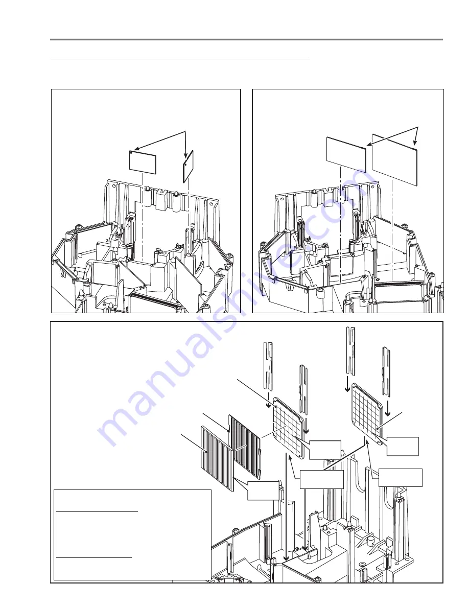
6-2. Optical Parts Directions in the Optical Unit
When mounting or assembling the optical parts in the optical unit, the parts must be mounted in the specified location
and direction as shown in the figure below.
Polarized glass (IN/GB)
Place glasses as the marker comes top-left corner as
shown in the figure below.
PBS/Integrator lens
Mount them as shown in the figure below.
dichroic mirror
Place the dichroic mirrors as the marker comes top
right corner as shown in the figure below.
Marker
Marker
PBS
Light shield
Integrator-Out
Integrator-In
Stopper-D
Stopper-C
Stopper-B
Stopper-A
Rugged
surface
Rugged
surface
Notched
side
Mounting order of the Integrator Lens
Integrator-Out Mounting
Mount the Stopper-A first and then mount
the Integrator-Out and Stopper -B in se-
quence.
Integrator-In Mounting
Mount the Stopper-C first and then mount
the Integrator-In and Stopper-D in sequence.
Chop mark
Chop mark
Summary of Contents for PLC-XTC50AL
Page 99: ... 99 IC Block Diagrams ISL98001 A D Converter IC2201 L3E06170 S H IC501 IC531 IC561 ...
Page 100: ... 100 IC Block Diagrams M62393 DAC IC7971 L3E07111 LCD DRIVE DIGITAL GAMMA IC401 ...
Page 101: ... 101 IC Block Diagrams NJM2671 Motor Controller IC7601 LC87F2G08A MCU IC4501 ...
Page 102: ... 102 IC Block Diagrams PW392 Scaler IC301 PW610 Keystone IC2301 ...
Page 103: ... 103 IC Block Diagrams TE7783 I O Expander IC4801 TPA3123 Audio Output IC5051 ...
Page 104: ... 104 IC Block Diagrams UPC324GR Ope Amp IC1423 ...
Page 158: ... KH7AM Nov 2009 DC 200 Printed in Japan SANYO Electric Co Ltd ...


