


-14-
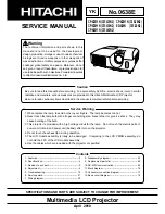
Mechanical Disassembly
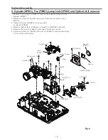
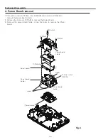
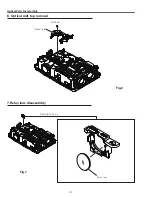
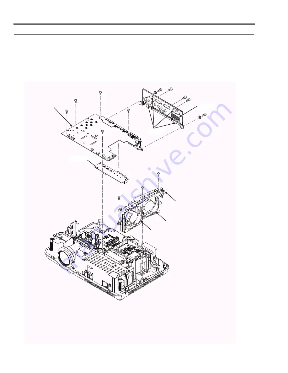
AV Panel
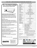
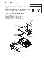
1. Remove 5 screws A (M.5x6) and screws B (M4x4) to remove the Main Board.
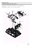
. Release the hooks to remove the AV Panel and remove 3 screws C (T3x6) to remove
the AV Board.
3. Remove 3 screws D (T3X8) to remove the fans (FN90 and FN906).
Fig.2
2. Main Board, AV Panel and Fan removal
A (M.5x6)x5
A
A
A
A
B (M4x4)x
B
Main Board
C (T3x6)x3
C C
AV Board
Hooks
D (T3x8)x3
Fan (FN90)
Fan (FN906)
SW901
D
D
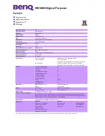
Summary of Contents for PLC-XU300A
Page 64: ... 64 IC Block Diagrams FA5550NG P F Control IC621 XR16L5701IL24 UART IC9885 ...
Page 68: ... 68 IC Block Diagrams MR4010 Power OSC IC631 PIC18F67J60 LAN CONTROL IC8801 ...
Page 69: ... 69 IC Block Diagrams FA7703 DC DC Converter IC7811 ...
Page 97: ...KF5 XU350A00 KA5 XU300A00 97 Mechanical Parts List ...
Page 98: ... KF5AE KA5AE December 2009 DC 200 Printed in Japan SANYO Electric Co Ltd ...
Page 108: ...A10 SCH_KF5AE SCH_KA5AE NO DATA ...