- 26 -
11
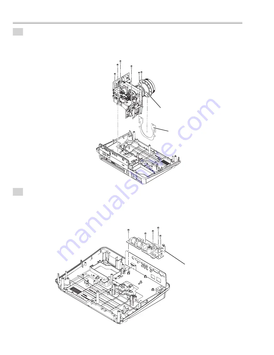
Optical unit removal.
1.Remove the screw-A(M3x6), remove the 5 screws-B(T3x10), remove the Optical unit and remove
the Spacer sheet bottom.
A
B
B
B
B B
Fig. 11
Optical unit
Spacer sheet bottom
12
Filter board removal.
1.Remove the 4 screws-A(T3x8), remove the screw-B(M3x6) and remove the Filter board.
A
A A
A
B
Fig. 12
Filter board
Mechanical disassemblies
Summary of Contents for PLV-Z4
Page 91: ... 91 SiI9011 HDMI Receiver IC8001 IC Block Diagrams ...
Page 112: ...M4W Z400 112 Mechanical and Optical Parts List 9 43 44 S5 S14 S12 S5 55 54 25 76 ...
Page 113: ...M4W Z400 113 Mechanical and Optical Parts List 1 12 5 46 45 61 51 47 49 ...
Page 115: ...M4W Z400 115 Mechanical and Optical Parts List 64 52 63 57 66 66 65 65 56 ...
Page 117: ...M4W Z400 117 Mechanical and Optical Parts List S7 S7 S10 S10 103 70 69 68 S7 S10 109 71 67 ...
Page 122: ...M4W Z400 MEMO 122 ...
Page 123: ...M4W Z400 123 MEMO ...
Page 124: ... M4WA Oct 2005 BB 400 Printed in Japan SANYO Electric Co Ltd ...
Page 138: ...Diagrams Drawings M4WA ...


