background image

3-100

Control of 3-WAY ECO-i SYSTEM

1

2

3

4

5

6

7

8

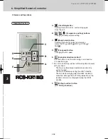
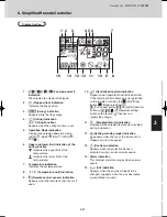
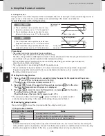
6. Simplifi ed Remote Controller

Connection diagram

How to wire the simplified remote controller

This multiple remote controller system controls 1 to 8 
indoor units with 2 simplified remote controllers.

1. One of the 2 simplified remote controllers should be set as 

main controller.

2. For the rest, see the “Remote controller setting mode” 

section and set up Sub.

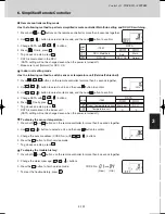
1. Following is a wiring diagram for controlling 1 indoor unit by 

2 simplified remote controllers.

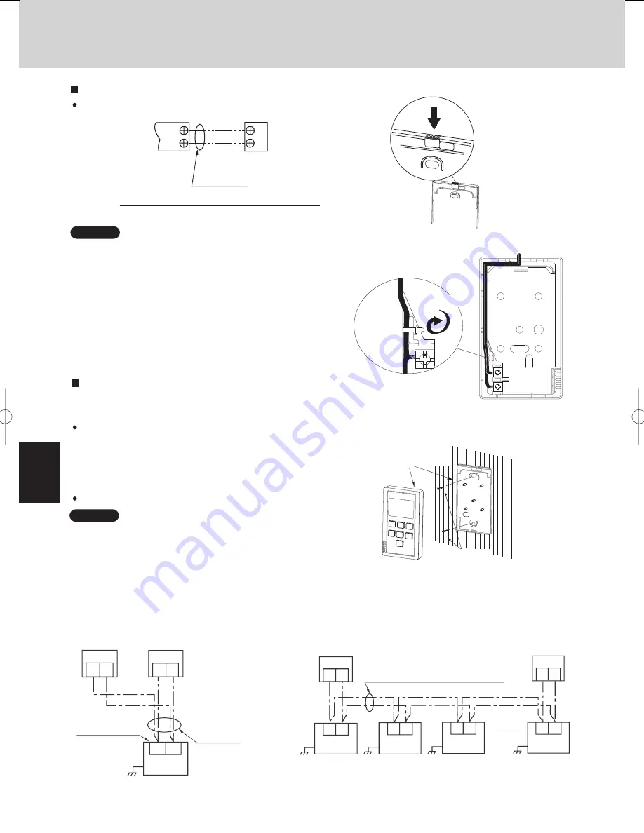
2. Performing group control of the multiple indoor units with 

2 simplified remote controllers.

3. The main and the sub simplified remote controllers can be 

installed at any indoor unit for operations.

Basic wiring diagram

Set-up procedure

Guidelines for using 2 simplified remote controllers

1. Do not twist the simplified remote controller wiring 

with the power wiring or run it in the same metal 
conduit, because this may cause malfunction.

Make sure to connect the wires correctly or the unit 
may be damaged. (See Fig. 3-70)

2. Install the simplified remote controller away from 

sources of electrical noise.

3. Install a noise filter or take other appropriate action 

if electrical noise affects the power supply circuit of 
the unit.

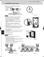
• Use an electric junction box (supplied locally) 

(See Fig. 3-64) for flush mounting of the simplified 
remote controller

Fig. 3-66

1
2

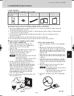
Wiring for simplified remote 

controller (supplied locally)

Simplified 

remote 

controller

*1: Use 0.5 mm

2

 to 1.25 mm

2

 stranded wires.

Terminal block 

for wiring 

the remote 

controller of the 

indoor unit

*1

1
2

Fig. 3-67

Fig. 3-68

Fig. 3-69

Binding strap

Simplified remote 
controller

Wood screws

Fig. 3-70

1 2

2

1

1 2

Simplified remote 

controller (main) 

Simplified remote 

controller (sub)

2-pin terminal block 

for remote controller 

wiring

Remote 

controller 

wiring 

(field supply)

Indoor unit

Earth

Fig. 3-71

Simplified remote 
controller (main) 

Simplified remote
controller (sub)

1

1

1

2

2

2

2

1

1 2

2

1

Inter indoor unit wiring for group control 
(supplied locally)

2-pin Terminal 
block for 
remote controller 
wiring

Indoor unit

No. 1

Indoor unit

No. 2

Indoor unit

No. 3

Indoorunit

No. 8

Earth

Earth

Earth

Earth

NOTE

NOTE

TD831143-00̲W-3WAY.indb   100

TD831143-00̲W-3WAY.indb   100

2008/12/01   10:26:50

2008/12/01   10:26:50

Summary of Contents for RCS KR1 EG

Page 1: ...3 4 3 ...

Page 2: ...y installation procedures incorrectly Precautions for Use Do not touch switches with wet hands 1 2 Electric shock and damage to the system can result Protect the remote controller from water Damage to the system can result Stop the system and turn the power off if you sense unusual smells or other irregularities 3 4 Continuing operation when the system is out of order can result in electric shock ...

Page 3: ... button Changing the fan speed E Swing Air direction button 1 Use this button to set the auto swing or air direction to a specific angle 1 Do not move the flap vertical airflow adjustment board with your hand The flap is automatically directed down when the unit is stopped The flap is directed up during the HEAT standby The flap starts swinging after the HEAT standby is cancelled although the AUTO...

Page 4: ...ower limit of the temperature 9 Remote control sensor indication Appears when the remote control sensor is used 10 Centralized control indication Appears when operated in centralized control If the remote control operation is not permitted to the remote unit when the Start Stop Fan speed button Swing Air direction button or Temperature setting buttons are pressed flashes and rejects the change 11 ...

Page 5: ...tioner s stop order stated in above is valid only when the outing function is operated If operated using other remote control unit or a centralized control device such as a system control the outing function does not work Setting the Outing Function Canceling the outing function Press and hold for more than 4 seconds while the outing function is set Outing function indication Outing function indic...

Page 6: ...back case when securing it Deformation of the back case may result in the remote controller falling off Do not apply excessive strain to the back case when securing it Deformation of the back case may result in the remote controller falling off 3 Connect the simplified remote controller wiring to the simplified remote controller main unit See How to wire the simplified remote controller When conne...

Page 7: ...es correctly or the unit may be damaged See Fig 3 70 2 Install the simplified remote controller away from sources of electrical noise 3 Install a noise filter or take other appropriate action if electrical noise affects the power supply circuit of the unit Use an electric junction box supplied locally See Fig 3 64 for flush mounting of the simplified remote controller Fig 3 66 1 2 Wiring for simpl...

Page 8: ...switch sensor or temperature unit Celsius Fahrenheit Indoor unit setting mode 1 2 3 5 4 Press buttons on the remote controller for more than 4 seconds together Use button to select a unit and then use button to confirm Use button to select an item code and then use button to confirm Change DATA with buttons Press Finally press To go back one step press To display the trouble history 1 2 3 To displ...

Reviews: