background image

31

s

n

o

i

t

i

d

n

o

c

/

l

o

r

t

n

o

C

n

o

i

t

a

r

e

p

o

t

i

n

U

n

o

i

t

a

n

a

l

p

x

E

R

O

S

N

E

S

Y

R

D

operation

F

F

O

/

N

O

e

h

T
button on the remote
controller is pressed.

.

s

e

t

a

n

i

m

u

l

l

i

p

m

a

l

n

o

i

t

a

r

e

p

o

e

h

T

n

a

f

t

e

s

e

h

t

t

a

s

e

t

a

r

e

p

o

n

a

f

r

o

o

d

n

i

e

h

T

.

d

e

e

p

s

.

s

p

o

t

s

t

i

n

u

r

o

o

d

t

u

o

e

h

T

3

r

o

f

e

t

a

r

e

p

o

t

o

n

s

e

o

d

t

i

n

u

r

o

o

d

t

u

o

e

h

T
minutes even after the breaker is turned ON.

.

s

t

r

a

t

s

t

i

n

u

r

o

o

d

t

u

o

e

h

T

)

.

t

r

a

t

s

n

a

f

r

o

o

d

t

u

o

e

h

t

d

n

a

r

o

s

s

e

r

p

m

o

C

(

1

f

o

e

t

a

r

e

h

t

t

a

d

e

s

a

e

r

c

n

i

s

i

y

c

n

e

u

q

e

r

f

e

h

T

.

s

d

n

o

c

e

s

5

.

0

y

r

e

v

e

z

H

s

e

h

c

a

e

r

y

c

n

e

u

q

e

r

f

e

h

t

n

e

h

W

α

,

z

H

d

o

i

r

e

p

a

r

o

f

d

e

p

p

o

t

s

e

r

a

s

e

s

a

e

r

c

n

i

y

c

n

e

u

q

e

r

f

f

o

β

)

.

1

e

l

b

a

T

o

t

r

e

f

e

R

(

.

s

d

n

o

c

e

s

o

t

l

i

o

f

o

n

r

u

t

e

r

e

h

t

e

z

i

l

i

b

a

t

s

o

t

r

e

d

r

o

n

i

s

i

s

i

h

T

.

r

o

s

s

e

r

p

m

o

c

e

h

t

.

s

e

s

a

e

r

c

n

i

n

e

h

t

y

c

n

e

u

q

e

r

f

e

h

T

e

r

a

s

e

r

u

t

a

r

e

p

m

e

t

r

o

o

d

t

u

o

d

n

a

r

o

o

d

n

i

e

h

t

f

I

,

s

e

t

a

v

i

t

c

a

f

f

o

-

t

u

c

k

a

e

p

t

n

e

r

r

u

c

e

h

t

,

h

g

i

h

.

y

c

n

e

u

q

e

r

f

n

i

s

e

s

a

e

r

c

n

i

y

n

a

g

n

i

p

p

o

t

s

e

r

u

t

a

r

e

p

m

e

t

m

o

o

r

e

h

T

d

e

r

i

s

e

d

e

h

t

s

e

h

c

a

e

r

e

r

e

h

t

d

n

a

,

e

r

u

t

a

r

e

p

m

e

t

r

e

h

t

r

u

f

r

o

f

d

e

e

n

o

n

s

i

.

g

n

i

l

o

o

c

.

s

t

r

a

t

s

n

o

i

t

a

r

e

p

o

Y

R

D

o

t

r

e

d

r

o

n

i

d

e

z

i

l

i

b

a

t

s

s

i

y

c

n

e

u

q

e

r

f

g

n

i

t

a

r

e

p

O

.

t

n

e

m

n

o

r

i

v

n

e

e

l

b

a

t

r

o

f

m

o

c

a

n

i

a

t

n

i

a

m

n

o

i

t

a

r

e

p

o

A

Y

R

D

n

e

e

w

t

e

b

s

e

g

n

a

h

c

n

a

f

r

o

o

d

n

i

e

h

T
“Low” and “LL” (very low) over a 6-minute

.

n

o

i

t

a

r

e

p

o

n

a

f

n

o

i

t

a

u

t

c

u

l

f

f

/

1

s

i

s

i

h

T

.

e

l

c

y

c

g. 1 below.)

i

F

o

t

r

e

f

e

R

(

r

i

a

e

h

t

y

f

i

d

i

m

u

h

e

d

y

l

e

v

i

t

c

e

f

f

e

o

t

s

e

t

a

r

e

p

O

r

o

o

d

n

i

e

h

t

g

n

i

c

u

d

e

r

y

l

e

v

i

s

s

e

c

x

e

t

o

n

e

l

i

h

w

.

e

r

u

t

a

r

e

p

m

e

t

n

o

i

t

a

u

t

c

u

l

f

f

/

1

t

a

s

e

t

a

r

e

p

o

t

i

n

u

r

o

o

d

n

i

e

h

T

t

o

n

s

e

o

d

t

a

h

t

d

e

e

p

s

n

a

f

a

t

a

,

n

o

i

t

a

r

e

p

o

n

a

f

.

g

n

i

l

e

e

f

y

l

l

i

h

c

a

e

s

u

a

c

e

r

u

t

a

r

e

p

m

e

t

m

o

o

r

e

h

T

d

n

a

,

r

e

h

g

i

h

r

o

C

°

5

1

s

i

.

d

l

o

c

o

o

t

y

l

t

h

g

i

l

s

s

i

n

o

i

t

a

r

e

p

o

B

Y

R

D

n

e

e

w

t

e

b

s

e

g

n

a

h

c

n

a

f

r

o

o

d

n

i

e

h

T
“Low” and “LL” (very low) over a 6-minute

.

n

o

i

t

a

r

e

p

o

n

a

f

n

o

i

t

a

u

t

c

u

l

f

f

/

1

s

i

s

i

h

T

.

e

l

c

y

c

1

e

h

t

,

s

e

t

u

n

i

m

3

y

l

e

t

a

m

i

x

o

r

p

p

a

r

e

t

f

A

n

a

f

r

o

o

d

t

u

o

e

h

t

,

F

F

O

s

n

r

u

t

r

o

s

s

e

r

p

m

o

c

.

F

F

O

s

n

r

u

t

n

a

f

r

o

o

d

n

i

e

h

t

d

n

a

,

F

F

O

s

n

r

u

t

e

h

t

,

s

e

t

u

n

i

m

6

y

l

e

t

a

m

i

x

o

r

p

p

a

r

e

t

f

A

n

i

e

s

o

h

t

o

t

n

r

u

t

e

r

s

n

o

i

t

i

d

n

o

c

1

.

,

N

O

s

e

t

u

n

i

m

-

3

a

n

o

s

e

t

a

r

e

p

o

r

o

s

s

e

r

p

m

o

c

e

h

T

m

o

o

r

e

h

t

t

n

e

v

e

r

p

o

t

,

e

l

c

y

c

F

F

O

s

e

t

u

n

i

m

-

6

.

h

c

u

m

o

o

t

g

n

i

p

p

o

r

d

m

o

r

f

e

r

u

t

a

r

e

p

m

e

t

e

r

u

t

a

r

e

p

m

e

t

m

o

o

r

e

h

T

.

C

°

5

1

w

o

l

e

b

s

i

.

s

n

i

g

e

b

n

o

i

t

a

r

e

p

o

g

n

i

r

o

t

i

n

o

M

e

h

t

,

s

n

i

g

e

b

n

o

i

t

a

r

e

p

o

g

n

i

r

o

t

i

n

o

m

n

e

h

W

s

e

t

a

r

e

p

o

n

a

f

r

o

o

d

n

i

e

h

t

d

n

a

,

s

p

o

t

s

r

o

s

s

e

r

p

m

o

c
at “LL” (very low) speed.

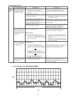
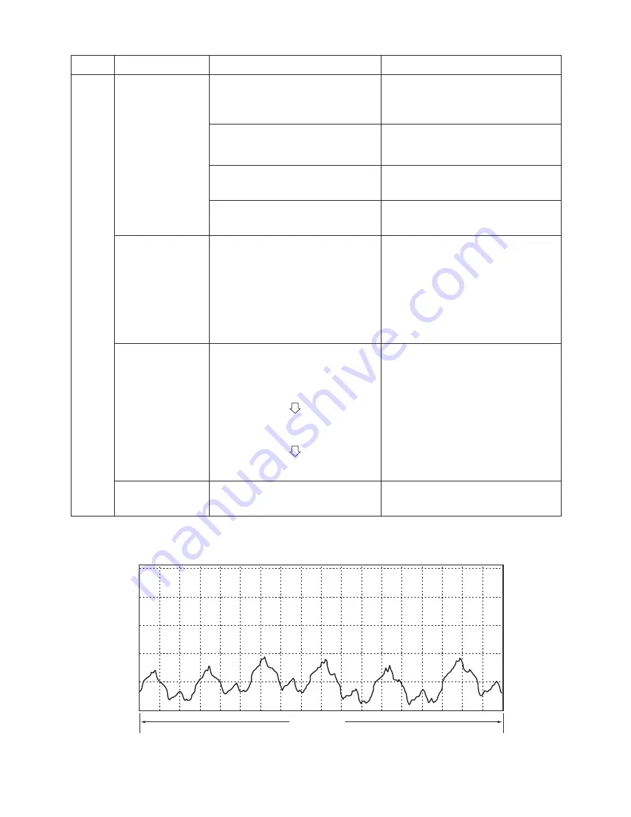
(1/f fluctuation fan)

 1/f fluctuation fan (SAP-KMRV, DMRV)

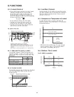
Fig. 1

6-minute cycle

250

200

150

(Step)

100

50

0

Summary of Contents for SAP-CMRV1923GJ

Page 1: ...Pay special attention when servicing the unit Combined Indoor Units 1 How these units may be combined is given in the Unit Combination Tables in the Appendix 2 Be sure to operate the air conditioning system only when 2 or more indoor units have been installed If operated with only a single unit installed the returning fluid to the compressor may cause a malfunction NOTE Concealed duct type SAP DMR...

Page 2: ...ing Be careful when picking up and moving the indoor and outdoor units Get a partner to help and bend your knees when lifting to reduce strain on your back Sharp edges or thin aluminum fins on the air conditioner can cut your fingers When Installing In a Ceiling or Wall Make sure the ceiling wall is strong enough to hold the unit s weight It may be necessary to construct a strong wood or metal fra...

Page 3: ...5 Wiring System Diagram 21 8 FUNCTIONS 8 1 Current Control 22 8 2 Low Start Current 22 8 3 Compressor Temperature Control 22 8 4 Outdoor Fan Control 22 9 TROUBLESHOOTING 9 1 Outdoor Unit Trouble Diagnostics 24 9 2 Checking the Outdoor System 25 9 3 Unit Problems and Inspection Points 26 9 4 Explanation of Functions 29 10 REFRIGERANT R410A SPECIAL PRECAUTIONS WHEN SERVICING UNIT 10 1 Characteristic...

Page 4: ...1 1 OPERATING RANGE Temperature Indoor Air Intake Temp Outdoor Air Intake Temp Cooling Maximum 32 C DB 23 C W B 43 C D B Minimum 19 C DB 14 C W B 19 C D B ...

Page 5: ...igerant Amount charged at shipment g R410A 2 500 Refrigerant control Electric Expansion Valve Operation sound Hi dB A 48 48 Refrigerant tubing connections Flare type Max allowable tubing length per unit m 25 Refrigerant Narrow tube mm in 6 35 1 4 2 tube diameter Wide tube mm in 9 52 3 8 2 Dimensions Weight Unit dimensions Height mm 730 Width mm 940 Depth mm 340 Package dimensions Height mm 831 Wid...

Page 6: ...rged at shipment g R410A 2 900 Refrigerant control Electric Expansion Valve Operation sound Hi dB A 48 48 Refrigerant tubing connections Flare type Max allowable tubing length per unit m 25 Refrigerant Narrow tube mm in 6 35 1 4 3 tube diameter Wide tube mm in 9 52 3 8 3 Dimensions Weight Unit dimensions Height mm 730 Width mm 940 Depth mm 340 Package dimensions Height mm 831 Width mm 1 016 Depth ...

Page 7: ...t off control YES Compressor discharge temp control YES Operation cut off control in abnormal ambient temp Run capacitor µF VAC Crankcase heater Fan Fan Motor Type Propeller Q ty Dia mm 1 ø460 Fan motor model Q ty KFC6S 61C4P C 1 No of poles rpm 220V High 6 670 Nominal output W 60 Coil resistance Ambient temp 20 C Ω WHT BRN 82 02 WHT YEL 41 94 YEL PNK 18 97 Safety devices Type Thermal protector Op...

Page 8: ...or discharge temp control YES Operation cut off control in abnormal ambient temp Run capacitor µF VAC Crankcase heater Fan Fan Motor Type Propeller Q ty Dia mm 1 ø460 Fan motor model Q ty KFC6S 61C4P C 1 No of poles rpm 220V High 6 670 Nominal output W 60 Coil resistance Ambient temp 20 C Ω WHT BRN 82 02 WHT YEL 41 94 YEL PNK 18 97 Safety devices Type Thermal protector Operating temp Open C 130 8 ...

Page 9: ...SAP CMRV2433GJ 0 0 10 20 30 40 50 60 70 80 90 40 60 80 100 120 140 160 180 200 20 Temperature C Compressor temp sensor Outdoor air temp sensor Narrow tube sensor Wide tube sensor 40 35 30 25 20 15 10 5 0 20 15 10 5 0 5 10 15 20 Temperature C Resistance Ω Resistance Ω ...

Page 10: ...t SAP CMRV1923GJ 18 730 940 AIR INTAKE 465 25 25 25 25 296 13 13 19 20 15 10 380 405 340 13 13 660 110 Drain hole AIR DISCHARGE AIR INTAKE AIR INTAKE Unit mm 166 86 Wide tube service valve ø9 52 3 8 Narrow tube service valve ø6 35 1 4 ...

Page 11: ...23GJ 18 730 940 AIR INTAKE 465 25 25 25 25 296 13 13 19 20 15 10 380 405 340 13 13 660 110 Drain hole AIR DISCHARGE AIR INTAKE AIR INTAKE 246 166 86 Wide tube service valve ø9 52 3 8 Narrow tube service valve ø6 35 1 4 unit mm ...

Page 12: ...should be a min 8 mm After a tube has been insulated never try to bend it into a narrow curve because it can cause the tube to break or crack IMPORTANT CAUTION Wide tube Thickness Min 8 mm Insulation Narrow tube Thickness Min 8 mm Indoor unit Service valve on wide tube side Service valve on narrow tube Compressor Strainer Muffler Muffler Sub accumulator When cooling Outdoor heat exchanger Electric...

Page 13: ...in 8 mm After a tube has been insulated never try to bend it into a narrow curve because it can cause the tube to break or crack IMPORTANT CAUTION Wide tube Thickness Min 8 mm Insulation Narrow tube Thickness Min 8 mm Outdoor Unit SAP CMRV2423GJ 3 Room Multi Refrigerant Tubing System Diagram When cooling Outdoor heat exchanger Electric expansion valve Electric expansion valve Main accumulator Comp...

Page 14: ...n Hi fan Cooling Characteristics 1 Low pressure performance chart RH 46 Indoor fan speed High fan 2 Operating current performance chart RH 46 Indoor fan speed High fan 50 60Hz 220V 50 60Hz 220V 3 Indoor discharge air performance chart RH 46 Indoor fan speed High fan 50 60Hz 220V Operating current A Low pressure MPa Indoor discharge air temperature C Outdoor air temperature C Outdoor air temperatur...

Page 15: ...emperature C Outdoor air temperature C Outdoor air temperature C 27 C 24 C 24 C Indoor air temp 30 C Indoor air temp 30 C 27 C 27 C Indoor air temp 30 C 24 C Outdoor Unit SAP CMRV1923GJ Indoor Unit SAP KMRV183GJ 1 NOTE This performance chart shows operation of a single wall mounted indoor unit The performance chart will vary depending on the indoor unit type Check each performance value in test ru...

Page 16: ...r air temp 30 C 27 C 24 C Indoor air temp 30 C 27 C 24 C Lo fan Hi fan Lo fan Hi fan Lo fan Hi fan Cooling Characteristics 1 Low pressure performance chart RH 46 Indoor fan speed High fan 2 Operating current performance chart RH 46 Indoor fan speed High fan 50 60Hz 220V 50 60Hz 220V 3 Indoor discharge air performance chart RH 46 Indoor fan speed High fan 50 60Hz 220V Operating current A Low pressu...

Page 17: ...Hz 220V Operating current A Low pressure MPa Indoor discharge air temperature C Outdoor air temperature C Outdoor air temperature C Outdoor air temperature C Outdoor Unit SAP CMRV2433GJ Indoor Unit SAP KMRV183GJ 1 NOTE This performance chart shows operation of a single wall mounted indoor unit The performance chart will vary depending on the indoor unit type Check each performance value in test ru...

Page 18: ...2 FILTER PCB HS ORG 7 9 CN35 WHT 3 1 5 SI BRN TERMINAL BASE 3P 6 6 7 7 WHT BLK WHT PAM PAM CN23 4 4 5 5 WHT BLK WHT 1 1 2 2 BLK BLK WHT CT CT WHT CN08 1 1 3 3 BLK BLK WHT PRY PRV RED CN21 W W AC200 L2 CN29 BLK YEL YEL BLK YEL YEL YEL TH7 TH6 RED YEL 4 3 2 1 BTH CN22 TH5 TH4 TH2 TH1 WHT ORG BLU BRN YEL RED RED BLU ORG WHT YEL BRN BD C0 BLK WHT BLK WHT WHT WHT 3 GRY MC01 MC02 ORG GRY 6 TH3 1 BLK WHT...

Page 19: ... WHT ORG BLU RED RED YEL BRN BLU ORG WHT TH1 TH2 TH4 TH5 CN22 BTH 1 2 3 4 YEL YEL YEL RED TH6 TH7 CN20 CTH 1 2 3 4 YEL YEL YEL BLU TH8 TH9 BLK YEL YEL BLK CN29 AC200 L2 W W CN21 RED PRY PRY WHT BLK BLK 3 3 1 1 CN08 WHT CT CT WHT BLK BLK 2 2 1 1 WHT BLK WHT 5 5 4 4 CN23 PAM PAM WHT BLK WHT 7 7 6 6 TERMINAL BASE 3P BRN SI 5 1 3 WHT CN35 9 7 ORG HS FILTER PCB 2 2 BLK 1 1 BLK CN03 WHT HIC3 HIC3 CN18 W...

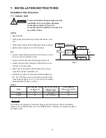
Page 20: ...outdoor unit and within a total tubing length L1 L2 L1 L2 L3 from the outdoor unit as detailed in Table 1 and Fig 1 Table 1 INDOOR UNIT 1 INDOOR UNIT 3 INDOOR UNIT 2 Tubing length L1 L2 L3 Elevation difference H1 H2 H3 OUTDOOR UNIT Fig 1 WARNING To prevent abnormal heat generation and the possibility of fire do not place obstacles enclosures and grilles in front of or surrounding the air condition...

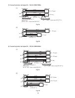
Page 21: ... m A φ6 35 φ6 35 φ9 52 φ9 52 A B 93 123 types Outdoor unit Indoor unit 183 type φ9 52 φ9 52 Less than 17 m B Fig 2a Fig 2b Fig 2c Fig 2d φ6 35 φ6 35 φ6 35 φ9 52 φ9 52 Union φ12 7 φ9 52 φ9 52 φ9 52 A B C 93 123 types Outdoor unit Indoor unit 93 123 types 183 type Flare φ9 52 Union φ12 7 φ12 7 Flare φ9 52 φ9 52 φ12 7 Optional parts STK 34TC φ12 7 φ9 52 Optional parts STK 43TCA A joint for connecting...

Page 22: ...at will not magnify operating noise or vibration Fasten in place with the anchor bolts M10 provide a base using concrete or similar material and ensure proper drainage select a location where there is no danger of flammable gas leakage in snowy or rainy regions be sure to construct a roof to keep off the snow and rain and inhibit freezing and condensation select a location that is at least 3 meter...

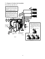
Page 23: ... with the indoor unit Use caution Connecting any other model may result in operation failure and malfunction The dimensions indicated by in the figure below are spaces that are required in order to maintain performance Install in a location where the dimensions indicated by are ensured and where 2 or more faces of the unit are unobstructed In principle the top direction should be unobstructed Cove...

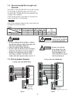
Page 24: ...supply Single phase AC 220 240 V B CAUTION Be sure to connect the power supply line to the outdoor unit as shown in the wiring diagram The indoor unit draws its power from the outdoor unit 7 5 Wiring System Diagram WARNING Be sure to comply with local codes on running the wire from the indoor unit to the outdoor unit size of wire and wiring method etc Each wire must be firmly connected No wire sho...

Page 25: ...lues shown in the table below 8 1 2 Current control The operating frequency upper limits shown in the figure below are established for frequency reduction and increase prohibit Example of operation for cooling Example of operation during cooling Operates at the target frequency at Point A and below Stops increases to the frequency between Points A and B Reduces the frequency by 1 Hz per 0 5 second...

Page 26: ... any electrified parts before the control circuit board LED red turns OFF If the outdoor control circuit board is normal approximately 60 seconds will be required for the charge to dissipate However allow at least 30 minutes for the charge to dissipate if it is thought there might be trouble with the outdoor control circuit board If the outdoor control circuit board fuse has blown approximately 30...

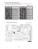
Page 27: ...bing D sensor narrow tubing Outdoor air temperature sensor Branch tubing A sensor wide tubing Branch tubing B sensor wide tubing Branch tubing C sensor wide tubing Branch tubing D sensor wide tubing CT current sensor HIC protective device current temperature OTP data failure Current peak exceeded Current control failure Active failure Compressor discharge temperature high Zero cross failure DC com...

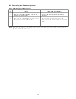
Page 28: ...cuit the T RUN terminal to the COM terminal NOTE If the above check items are okay but the outdoor unit does not operate there may be a faulty connection between the indoor unit and the outdoor unit Control No 1 2 The LED red on the control circuit board must illuminate The compressor and fan motor must turn ON They turn ON a few seconds after the power is turned ON Check items unit operation ...

Page 29: ...9 HIC Electrolytic capacitor Compressor Compressor protective thermistor Outdoor fan motor Coil thermistor Electric expansion valve Branch tubing temperature sensor Breaker Refrigerant gas pressure Measure during a test run Operation lamp flashes Indoor fan does not turn Operation lamp does not illuminate The compressor only does not operate The compressor stops on occasion The compressor speed do...

Page 30: ...ctive sensor compressor discharge temperature thermistor Check that the sensor is securely contained in the thermostat holder 9 3 6 Outdoor fan motor Turn the fan slowly by hand If the fan rotates easily a Replace the running capacitor on the outdoor control circuit board b Check for an open circuit in the fan motor coil winding c Use the tester AC range to check whether voltage is reaching the co...

Page 31: ...arged 2 3 times with refrigerant gas 200 g each time or if the change is small then the problem may not be refrigerant shortage The problem may be a blockage of the refrigerant circuit Check that the electric expansion valve is not blocked Check as described on the preceding page NOTE Cool the main unit with a damp cloth or other means while welding When applying vacuum use the special service mag...

Page 32: ... f o g n i n o i t i s o P d e p p o t s d e m r o f r e p s i e v l a v n o i s n a p x e operation F F O N O e h T button on the remote controller is pressed n e e b s a h e d o m n o i t a r e p o c i t a m o t u a f I n o i t a r e p o r e l l o r t n o c e t o m e r e h t h t i w d e t c e l e s begins in SENSOR DRY or COOL mode depending on the temperature at the time operation starts c i t ...

Page 33: ... h t s e t u n i m 3 r e t f A y l l a c i t a m o t u a g n i t a r e p o s i e c n a l a b e r u s s e r p a s e t u n i m 3 e s e h t g n i r u D t r a t s o t r o s s e r p m o c e h t g n i w o l l a d e v e i h c a y l i s a e e r o m n o i t n e v e r p e z e e r F t a e h r o o d n i e h t f o e r u t a r e p m e t e h t n e h W C 2 y l e t a m i x o r p p a o t s p o r d r e g n a h c x e...

Page 34: ...i a m n o i t a r e p o A Y R D n e e w t e b s e g n a h c n a f r o o d n i e h T Low and LL very low over a 6 minute n o i t a r e p o n a f n o i t a u t c u l f f 1 s i s i h T e l c y c g 1 below i F o t r e f e R r i a e h t y f i d i m u h e d y l e v i t c e f f e o t s e t a r e p O r o o d n i e h t g n i c u d e r y l e v i s s e c x e t o n e l i h w e r u t a r e p m e t n o i t a u ...

Page 35: ...refrigerant at its normal mixed composition state in liquid phase When refrigerant R410A is used the composition will differ depending on whether it is in gaseous or liquid phase and the basic performance of the air conditioner will be degraded if it is charged while the refrigerant is in gaseous state Thus always charge the refrigerant while it is in liquid phase 10 2 Checklist Before Servicing U...

Page 36: ...ng R22 and R407C No addition of compressor oil for R410A No additional charge of compressor oil is permitted No use of refrigerant other than R410A Never use a refrigerant other than R410A If refrigerant R410A is exposed to fire Through welding etc toxic gas may be released when R410A refrigerant is exposed to fire Therefore be sure to provide ample ventilation during installation work Caution in ...

Page 37: ...rging cylinder Refrigerant recovery unit Vacuum pump with anti reverse flow 1 Solenoid valve installed type which prevents oil from flowing back into the unit when the power is off is recommended Vacuum pump 2 can be used if the following adapter is attached Vacuum pump adapter reverse flow prevention adapter 3 Solenoid valve installed adapter attached to a conventional vacuum pump Electronic scal...

Page 38: ...alve installed vacuum pump so that even if power is cut off in the middle of evacuation of air due to a power interruption the valve will prevent the pump oil from flowing back The equipment may be damaged if moisture remains in the tubing thus carry out the evacuation thoroughly When using a vacuum pump with exhaust air volume more than 25L min and ultimate vacuum pressure rate of 0 05Torr Standa...

Page 39: ...76Kg using a capacity of a 10Kg cylinder the minimum necessary amount for the cylinder is 0 76 10 0 20 2 76Kg For the remaining refrigerant refer to the instructions of the refrigerant manufacturer If using a charging cylinder transfer the specified amount of liquid refrigerant from the refrigerant cylinder to the charging cylinder Prepare an evacuated charging cylinder beforehand Do not use the r...

Page 40: ... refrigerant other than R410A Also do not use oxygen or any flammable gas 5 Evacuation Use a solenoid valve installed vacuum pump so that even if power is cut off in the middle of evacuation of air due to a power interruption the valve will prevent the pump oil from flowing back The equipment may be damaged if moisture remains in the tubing thus carry out the evacuation thoroughly When using a vac...

Page 41: ...g 0 76Kg using a capacity of a 10Kg cylinder the minimum necessary amount for the cylinder is 0 76 10 0 20 2 76Kg For the remaining refrigerant refer to the instructions of the refrigerant manufacturer If using a charging cylinder transfer the specified amount of liquid refrigerant from the refrigerant cylinder to the charging cylinder Prepare an evacuated charging cylinder beforehand Do not use t...

Page 42: ...ant R410A for existing units which use R22 This will cause the air conditioner to operate improperly and may result in a hazardous condition 10 8 2 Use of Existing Tubing If replacing an older unit that used refrigerant R22 with a R410A unit do not use its existing tubing Instead completely new tubing must be used CAUTION Never charge additional refrigerant if refrigerant is leaking from the unit ...

Page 43: ...LES APPENDIX Be sure to operate the air conditioning system only when 2 or more indoor units have been installed If operated with only a single unit installed the returning fluid to the compressor may cause a malfunction NOTE ...

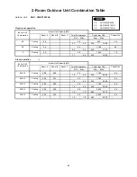
Page 44: ...oom B Room C Total Performance Power Input W Current A Min Max Min Max 2 8 2 8 Cooling 2 80 2 80 5 6 1 790 8 5 1 4 6 5 540 2 060 2 8 3 6 Cooling 2 45 3 15 5 6 1 790 8 5 1 4 6 5 540 2 060 3 6 3 6 Cooling 2 80 2 80 5 6 1 790 8 5 1 4 6 5 540 2 060 2 8 5 0 Cooling 2 00 3 60 5 6 2 030 9 6 1 2 7 0 480 2 270 3 6 5 0 Cooling 2 35 3 25 5 6 2 030 9 6 1 2 7 0 480 2 270 Outdoor Unit SAP CMRV1923GJ 2 8 SAP MRV...

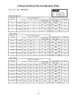
Page 45: ...620 2 380 3 6 5 0 Cooling 2 85 3 95 6 8 2 040 9 7 1 4 8 1 620 2 380 Three room operatio Indoor unit Indoor Unit Capacity kW Conbination Room A Room B Room C Total Performance Power Input W Current A Min Max Min Max 2 8 2 8 2 8 Cooling 2 26 2 26 2 26 6 8 2 040 9 7 1 4 8 1 620 2 380 2 8 2 8 3 6 Cooling 2 07 2 07 2 65 6 8 2 040 9 7 1 4 8 1 620 2 380 2 8 2 8 5 0 Cooling 1 80 1 80 3 20 6 8 2 040 9 7 1 ...

Page 46: ...SANYO Electric Co Ltd Osaka Japan SM700540 MAY 2003 Printed in Japan ...

Reviews: