background image

GB

FR

INSTALLATION INSTRUCTIONS

NOTICE D’INSTALLATION

Pub. ??.????.???.?

©SANYO 2009

SPW-W486HH58

SPW-W366HH58

SPW-W606HH58

Inverter split air to water heat pump - Indoor unit

Pompe à chaleur air / eau split inverter - Unité intérieure

(Name Plate)

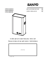
Summary of Contents for SPW-W366HH58

Page 1: ...LLATION INSTRUCTIONS NOTICE D INSTALLATION Pub SANYO 2009 SPW W486HH58 SPW W366HH58 SPW W606HH58 Inverter split air to water heat pump Indoor unit Pompe à chaleur air eau split inverter Unité intérieure Name Plate ...

Page 2: ...picking up and moving the indoor and outdoor units Get a partner to help and bend your knees when lifting to reduce strain on your back Sharp edges or thin aluminium fins on the air conditioner can cut your fingers When installing In a room Properly insulate any tubing run inside a room to prevent sweating which can cause dripping and water damage to walls and floors In moist or uneven locations U...

Page 3: ...at the voltage indicated on the unit corresponds to the mains voltage Before initiating maintenance or servicing on the installation check that its power supply is disconnected and locked out 1 4 USE OF EQUIPMENT This device is designed for heating buildings This appliance is not designed to be used by people including children whose physical sensory or mental capacities are impaired or who lack e...

Page 4: ... control 21 Cover 22 Communication module access window 23 Electrical box see detail below 2 PRESENTATION 2 1 DESCRIPTION 2 1 1 GENERAL SPW W366HH SPW W486HH SPW W606HH 12 11 8 4 3 10 9 5 7 6 2 1 1 Electrical cable passage 2 Terminal strip 3 Heating element circuit breakers 4 Heating element contactors 5 Circulator contactors 6 Fault relays 7 Water flow rate relay 8 Heating control board 9 Communi...

Page 5: ...pth 34 mm Colour White Class lll IP 30 2 1 3 ACCESSORIES INCLUDED WITH THE APPARATUS 2 2 DIMENSIONS AND WEIGHT Weight kg SPW W366HH 42 SPW W486HH 43 SPW W606HH 44 1 Water inlet connection 1 male 2 Water outlet connection 1 male 3 Water circuit fill drain 1 2 male 4 Safety valve connection and drainage 5 5 8 gas refrigerant connection 6 3 8 liquid refrigerant connection 7 Holes for electric cables ...

Page 6: ...ight 3 2 MOUNTING THE UNIT Remove the cover from the unit remove the retaining screws 1 on each side and 1 on top 1 Slide the cover upward 2 until the bottom edge of the covers is aligned with the lower part of the rear support then pull it towards you 3 Secure the unit to the wall Refer to the position of the 4 mounting holes in the diagram opposite Use anchors and screws not included that are ad...

Page 7: ...nnected on the 2 zone module thus doing away with the need to install the control unit in zone 1 Wall mounting the unit must not be installed in corners on shelves or behind curtains near sources or heat or directly exposed to sunlight The unit should be installed approximately 1 5 m above the floor Open the box by removing the lower screw and secure the base to the wall mounting holes item 1 Open...

Page 8: ... special oil which cannot tolerate the presence of other oils 2 The instruments used for filling pressure measurements emptying under vacuum recovering the fluid must be compatible and only used for the R 410 A fluid Note the pressure taps of the refrigerating circuit are 5 16 SAE 1 2 20 UNF 3 In the case of a new charge the charge must be undertaken in liquid phase use a balance and a dip pipe ty...

Page 9: ...ection install a shut off valve 3 not supplied 4 2 3 SAFETY VALVE CONNECTION The unit is equipped with a safety valve that opens if the pressure in the hydraulic system exceeds 3 bar A flexible hose 4 not supplied can be connected to the coupling insert coupling OD 18 mm 4 3 ELECTRICAL CONNECTION 4 3 1 GENERAL The acceptable voltage variation is 10 during operation The electrical connection condui...

Page 10: ...s The cable s shielding must be grounded at both ends by means of a metal clamp not supplied screwed onto the terminal strip support plate To avoid problems related to electromagnetic disturbances do not route this cable near power cables SPW W366 SPW W486 SPW W606 N L1 L2 L3 1 2 U1 U2 Three phase power supply 400V 3 N T 50Hz PE N Ph1 Ph2 Ph3 Terminal strip XA SPW W366 SPW W486 SPW W606 N L1 L2 L3...

Page 11: ... if any To be connected to the and terminals if terminal strip XB Refer to the ground shielding principle in paragraph 4 3 3 B Outside temperature sensor 2 conductor cable min size 0 5 mm2 Maximum length 25 meters To be connected to the heating board A1 Note This sensor must be located outside in a location that is representative of the temperature to be measured on a wall facing North North west ...

Page 12: ...inal unit zone or 2 mixed zones In the form of a potential free contact which can used in VLV Very Low Voltage 2A max To be connected to the heating board A1 Note The contact can control up to 10 RCC10 70250051 or RCC20 70250052 type controls Consult the terminal unit and remote control documentation to connect this contact CONTROL PART CONNECTION DIAGRAM Route the control cables on the right side...

Page 13: ...tors Power supply Bottom view of the indoor unit 5 ACCESSORIES 5 1 WATER CONNECTION HOSES Length 1 m insulated female Ø 1 code 70600055 for SPW W366 486 and 606 6 STARTING Before carrying out any work on the installation make sure that it is switched off and that access to it is prevented Any work must be carried out by personnel qualified and authorised to work on this type of machine IMPORTANT N...

Page 14: ...od condition of the apparatus No tools or other foreign objects inside the apparatus 6 2 CONFIGURATION AND PARAMETERISATION 6 2 1 AUTO ADDRESSING OF INDOOR AND OUTDOOR UNITS Set the control unit selector to OFF Turn on the indoor and outdoor units The unit cycles through an automatic addressing phase when the power is first turned on This phase may take 2 to 3 minutes and is indicated by the alter...

Page 15: ...stallation manual 6 3 ADDITIONAL HYDRAULIC CIRCUIT VERIFICATIONS 6 3 1 FORCED CIRCULATOR OPERATION In order to conduct the final verifications of the hydraulic circuit force the pump to start as follows installation power ON Set the system control unit to OFF Press and hold the button for 5 seconds The circulator starts The circulator indicator light flashes Check that the H2O flow indicator is il...

Page 16: ...rate Improperly purged water system If the manual thermostat trips correct the fault then reset the thermostat as follows Turn off and lock out the unit Remove the cover The thermostats are located against the heater partition on the front see paragraph 2 1 1 Press the button in the centre of the manual thermostat 7 3 PROTECTION OF HEATER CIRCUITS The heater features three heating elements each su...

Page 17: ...placement with other than genuine parts all modifications of the refrigerating circuit all replacement of refrigerant by a fluid other than that indicated on the manufacturer s plate all use of the unit outside the application limits defined in the documentation shall result in the cancellation of PED EC marking compliance which shall fall under the liability of the individual who carried out thes...

Page 18: ...C D1 D2 A3 H1 H2 H3 E1 E2 T T 230V A1 A2 KM2 A1 A2 KM3 A1 A2 KA1 R3 Q4 1 2 3 4 KM3 Q3 Q2 Q1 KM2 PE XA F2 CX6 F1 E1 CX4 CX3 P BUS CX1 A1 A2 KA2 S1 S2 S3 11 KA1 12 14 J1 11 KA2 12 14 S4 S5 S6 TR A1 M1 1 2 3 4 KM4 A2 A1 A2 KM4 U1 XB U2 XB PK U1 L3 L2 XB XB L1 IU PCB CC1 230V POMPE SYS COM GR 9 8 H2O 4 3 21 KA2 22 24 R1 R2 N XA L1 XA L2 XA L3 XA 1 2 3 4 1 2 3 4 KM1 23 XA 22 XA 19 XA 20 XA 21 XA BU U2 ...

Page 19: ...19 GB ...

Page 20: ...lles de commande Utilisez des câbles séparés pour chaque type de ligne Lors du transport Soyez prudent lorsque vous soulevez et déplacez les appareils intérieur et extérieur Demandez à un collègue de vous aider et pliez les genoux lors du levage afin de réduire les efforts sur votre dos Les bords acérés ou les ailettes en aluminium mince se trouvant sur le climatiseur risquent de vous entailler le...

Page 21: ...ension plaquée sur l appareil corresponde bien à celle du réseau Avant d intervenir sur l installation vérifier que celle ci est hors tension et consignée 1 4 USAGE Cet appareil est destiné au chauffage de locaux Cet appareil n est pas prévu pour être utilisé par des personnes y compris les enfants dont les capacités physiques sensorielles ou mentales sont réduites ou des personnes dénuées d expér...

Page 22: ...débit 21 Capot 22 Fenêtre d accès au module de communication 23 Coffret électrique voir détail ci dessous 2 PRÉSENTATION 2 1 DESCRIPTION 2 1 1 GÉNÉRALE SPW W366HH SPW W486HH SPW W606HH 12 11 8 4 3 10 9 5 7 6 2 1 1 Passage des câbles électriques 2 Bornier de raccordement 3 Disjoncteurs résistances électriques 4 Contacteurs résistances électriques 5 Contacteurs circulateur 6 Relais de défaut 7 Relai...

Page 23: ...lasse lll IP 30 2 1 3 ACCESSOIRES LIVRÉS AVEC L APPAREIL 2 2 DIMENSIONS ET POIDS Poids kg SPW W366HH 42 SPW W486HH 43 SPW W606HH 44 1 Raccordement entrée d eau 1 mâle 2 Raccordement sortie d eau 1 mâle 3 Remplissage vidange circuit d eau 1 2 mâle 4 Raccordement et évacuation soupape de sécurité 5 Raccordement liaison frigorifique gaz 5 8 6 Raccordement liaison frigorifique liquide 3 8 7 Passage de...

Page 24: ...ur adapté au poids de l appareil 3 2 MONTAGE DE L UNITÉ Retirer le capot de l appareil enlever les vis de fixations 1 de chaque côté et 1 sur le dessus 1 Faire glisser le capot vers le haut 2 jusqu à aligner le bas du capot avec la partie inférieure du support arrière puis tirer vers soi 3 Fixer l appareil au mur Voir la position des 4 trous de fixation ci contre Utiliser des chevilles et vis non ...

Page 25: ...soire sur le module 2 zones et éviter ainsi le montage du boîtier de commande dans la zone 1 Montage mural le boîtier ne doit être installé ni dans des coins des étagères ou derrière des rideaux ni au dessus ou à proximité de sources de chaleur et ne doit pas être exposé aux rayons du soleil La hauteur de montage est d environ 1 5 m au dessus du sol Ouvrir le boîtier en enlevant la vis inférieure ...

Page 26: ...ice d installation car la charge doit tenir compte de la longueur des liaisons 4 En cas de fuite ne pas compléter la charge récupérer le fluide restant pour le recyclage et refaire la charge totale La récupération le recyclage ou la destruction du fluide devront se faire en accord avec les lois en vigueur dans le pays concerné 5 En cas d ouverture du circuit frigorifique il est impératif d éviter ...

Page 27: ...iliser 4 2 3 RACCORDEMENT SOUPAPE DE SÉCURITÉ L appareil est équipé d une soupape de sécurité qui s ouvre si la pression du circuit hydraulique dépasse 3 bar On peut raccorder un tuyau souple 4 non fourni sur le raccord cannelé ø extérieur du raccord 18 mm 4 3 RACCORDEMENTS ÉLECTRIQUES 4 3 1 GÉNÉRALITÉS La tolérance de variation de tension acceptable est de 10 pendant le fonctionnement Les canalis...

Page 28: ... maximum 70 mètres Le blindage du câble doit être mis à la terre des deux côtés grâce à un collier métallique non fourni vissé sur la platine support bornier Ne pas faire cheminer ce câble à proximité de câbles de puissance pour éviter les problèmes d interférences électromagnétiques 10 FR SPW W366 SPW W486 SPW W606 N L1 L2 L3 1 2 U1 U2 Alimentation triphasée 400V 3 N T 50Hz PE N Ph1 Ph2 Ph3 Borni...

Page 29: ...boîtier de commande liaison unité intérieure module 2 zones éventuel À raccorder sur les bornes et du bornier XB Voir principe de mise à la terre du blindage au paragraphe 4 3 3 B Sonde de température extérieure Câble 2 conducteurs section minimum 0 5 mm2 Longueur maximum 25 mètres À raccorder sur la carte chauffage A1 Nota Cette sonde doit être placée à l extérieur dans un endroit représentatif d...

Page 30: ... terminales ou 2 zones mixtes Sous forme de contact libre de potentiel utilisable en TBT Très Basse Tension 2A résistif maximum À raccorder sur la carte chauffage A1 Nota Le contact peut piloter au maximum 10 commandes type RCC10 70250051 ou RCC20 70250052 Consulter la notice des unités terminales et des commandes à distance pour le raccordement de ce contact SCHÉMA DE RACCORDEMENT DE LA PARTIE CO...

Page 31: ...érieure Fil pilote convecteurs électriques Alimentation Vue du dessous de l unité intérieure 5 ACCESSOIRES 5 1 FLEXIBLES RACCORDEMENT D EAU Longueur 1 m isolés raccordement femelle Ø 1 code 70600055 pour SPW W366 486 et 606 6 MISE EN SERVICE Avant toute intervention sur l installation s assurer de sa mise hors tension et de sa consignation Toute intervention doit être réalisée par du personnel qua...

Page 32: ...reil Absence d outils et autres objets étrangers dans l appareil 6 2 CONFIGURATION ET PARAMÉTRAGE 6 2 1 AUTOADRESSAGE DES UNITÉS INTÉRIEURE ET EXTÉRIEURE Mettre le selecteur du boîtier de commande sur arrêt OFF Mettre sous tension les unités intérieure et extérieure Lors de la première mise sous tension une phase d adressage automatique se déroule Cette phase peut durer 2 à 3 minutes et est signal...

Page 33: ...a notice régulation système 6 3 VÉRIFICATIONS COMPLÉMENTAIRES CIRCUIT HYDRAULIQUE 6 3 1 MISE EN MARCHE FORCÉE DU CIRCULATEUR Pour faire les dernières vérifications du circuit hydraulique démarrer la pompe en marche forcée comme suit installation sous tension Mettre le boîtier de commande système sur arrêt OFF Appuyer pendant 5 secondes sur le bouton Le circulateur démarre Le voyant circulateur cli...

Page 34: ...t Circuit d eau mal purgé Si le thermostat manuel déclenche remédier au défaut puis réarmer le thermostat comme suit Mettre hors tension et consigner l appareil Enlever le capot Les thermostats se trouvent contre la paroi du réchauffeur sur le devant voir paragraphe 2 1 1 Appuyer sur le bouton au centre du thermostat manuel 7 3 PROTECTION DES CIRCUITS DU RÉCHAUFFEUR Le réchauffeur possède 3 résist...

Page 35: ...ar une pièce autre que celle d origine toutes modifications du circuit frigorifique tout remplacement du fluide frigorigène par un fluide différent de celui indiqué sur la plaque signalétique toute utilisation de l appareil en dehors des limites d applications figurant dans la documentation entraîneraient l annulation du marquage CE conformité à la PED le cas échéant qui deviendrait sous la respon...

Page 36: ... D1 D2 A3 H1 H2 H3 E1 E2 T T 230V A1 A2 KM2 A1 A2 KM3 A1 A2 KA1 R3 Q4 1 2 3 4 KM3 Q3 Q2 Q1 KM2 PE XA F2 CX6 F1 E1 CX4 CX3 P BUS CX1 A1 A2 KA2 S1 S2 S3 11 KA1 12 14 J1 11 KA2 12 14 S4 S5 S6 TR A1 M1 1 2 3 4 KM4 A2 A1 A2 KM4 U1 XB U2 XB PK U1 L3 L2 XB XB L1 IU PCB CC1 230V POMPE SYS COM GR 9 8 H2O 4 3 21 KA2 22 24 R1 R2 N XA L1 XA L2 XA L3 XA 1 2 3 4 1 2 3 4 KM1 23 XA 22 XA 19 XA 20 XA 21 XA BU U2 O...

Page 37: ...19 FR ...

Page 38: ...SANYO Airconditioners Europe S r l Via Bisceglie No 76 20152 Milano Italy SAN 10 11 525 GB FR 00 ...

Reviews: