LOCATIONS OF CONTROLS AND INDICATORS
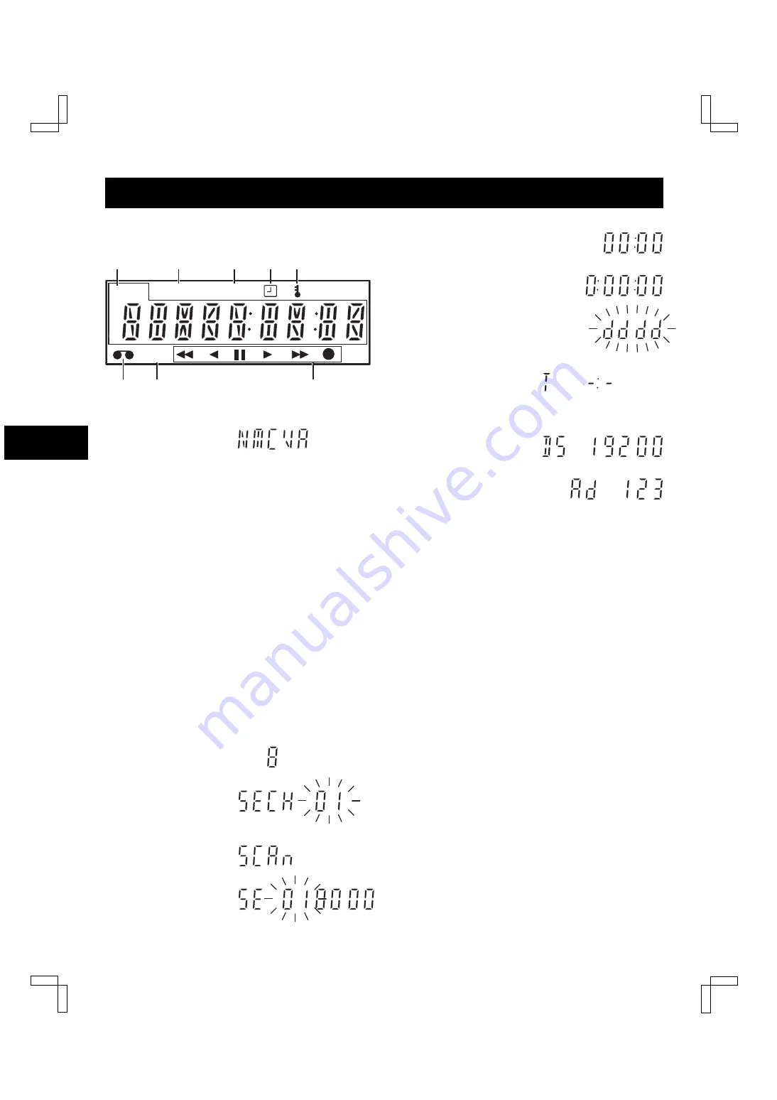
Digital Display
1
Mode display
œ
Warning display
N flashes:
Mode changed to non-recording
mode while recording was in progress.
M flashes: Problem with mechanism.
C flashes:
Clog detection has occurred.
V flashes:
Video loss has occurred.
A flashes:
Alarm recording in progress.
When alarm recording finishes, AL
lights.
AL flashes during alarm recording.
NOTES:
œ
The warning details appear according to the
(WARNING OUT/CONTROL SET) menu
setting.
œ
The warning display has priority over other
types of display. (Refer to “WARNING OUT
Terminal” on page 46.)
œ
To cancel the display press the STOP button.
œ
Recording/playback
speed mode
œ
Alarm search
setting display
œ
Alarm scan setting
display
œ
Day/Time search
setting display
œ
Time display (No tape)
œ
Linear time counter
display (Tape inserted)
œ
Dew display
œ
Tracking control
display
[With the RS-485 interface board]
œ
Data transfer speed
setting display
œ
Address setting display
2
Power failure indicator
P
Lights after a power failure.
NOTE:
œ
To cancel the “P” display, press the MENU
RESET button.
3
External input indicator
Lights when recording using the EXT TIMER IN
input terminal.
4
Timer Recording indicator
Lights when in timer recording stand-by mode, or
during a timer recording.
5
Security lock indicator
Lights when the security lock is engaged.
M
E
P
T/D
AL
OFF
2
3
6
8
5
1
7
4
AL
AL
AL
T/D
NB4QR/NA (SRT-4040 GB) Tue. Sept., 10/2002
English
5


