background image

OUTPUT TERMINALS

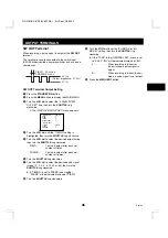
SW OUT Terminal

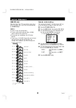
When recording, a pulse signal is output at the SW OUT
terminal.

This terminal is usually connected to the switch input
(SW IN) of devices like a camera switcher unit, or a quad
compressor.

SW OUT Terminal Output Setting

1

Press the STANDBY/ON button.

2

Press the MENU button to display the MAIN MENU.

3

Turn the JOG dial to select the “2.DISPLAY/SW
OUT SET” line, then turn the SHUTTLE ring
clockwise.

ø

The (DISPLAY/SW OUT SET) menu appears.

<DISPLAY@SET>@@@@SET@UP

DATE@@@@@@@@@@@@@Y

TIME@@@@@@@@@@@@@Y

SPEED@@@@@@@@@@@@Y

ALARM@COUNT@@@@@@Y

<SW@OUT@SET>

TIMING@@@@@@@@@@@FIELD

FIELD@@@@@@@@@@@@1

8H@MODE@@@@@@@@@@Y

4

Turn the JOG dial until the “TIMING” setting is
highlighted, then turn the SHUTTLE ring clockwise.

5

Turn the JOG dial to select the desired output timing,
then turn the SHUTTLE ring clockwise.

FIELD. . . . . .  1 pulse is output after each set

number of fields.

FRAME . . . .  1 pulse is output after each set

number of frames.

6

Turn the SHUTTLE ring clockwise.

7

Turn the JOG dial to select the desired pulse signal
interval (1, 2, 3, 4, 5, 10, 30 or 60), then turn the
SHUTTLE ring clockwise.

œ

If “TIMING” is set to FRAME (see step 

5

),

“FRAME” will be indicated instead of “FIELD”.

8

Turn the SHUTTLE ring clockwise.

9

Turn the JOG dial to set the “8H MODE (or 6H
MODE)” setting, then turn the SHUTTLE ring
clockwise.

œ

If the “TAPE” in the (GENERAL SET) menu is set
to “E-180”, “6H” will be indicated instead of “8H”.

Y. . . . . . . . . .  When recording in 8-hour (or

6-hour) mode, a pulse signal is
output.

N. . . . . . . . . .  When recording in 8-hour (6-hour)

mode, a pulse signal is not output.

F

Press the MENU EXIT button.

5V (H)

0V (L)

(Output impedance: 5.7 k

)

FIELD:   20 msec.
FRAME: 5 msec.

RQ4QR/EX (SRT-8960P GB)  Fri. Sept., 06/2002

46

English

Summary of Contents for SRT-8040P

Page 1: ...ograbador en tiempo real Español Videoregistratore a cassette in tempo reale Italiano Please read this manual carefully before connecting your VCR and operating it for the first time Be sure to read carefully and follow all the PRECAUTIONS on page 1 and 2 Keep the manual in a safe place for future reference RQ4QR EX SRT 8960P GB Fri Sept 06 2002 I index ...

Page 2: ...il leverandøren ADVARSEL Eksplosjonsfare ved feilaktig skifte av batteri Benytt samme batteritype eller en tilsvarende type andefalt av apparatfabrikanten Brukte batterier kasseres i henhold til fabrikantens instruksjoner VARNING Explosionsfara vid felaktigt batteribyte Använd samma batterityp eller en ekvivalent typ som rekommenderas av apparattillverkaren Kassera använt batteri enligt fabrikante...

Page 3: ...y the plug œ If any liquid is spilled on the VCR unplug the power cord immediately and have the unit inspected at a factory authorized service centre œ Do not place anything directly on top of this VCR Moisture Condensation Problems Cause When the VCR is first installed moved from a cold area to a warm area or placed in a location with high humidity dew moisture may form in the unit The Dew indica...

Page 4: ...st Forward Rewind œ Field recording playback œ Audio recording is available in 6 18 and 30 hour modes E 180 œ Audio recording is available in 8 24 and 40 hour modes E 240 œ Autorepeat recording œ Series recording function œ Alarm recording function œ Single image recording function œ On screen mode setting œ Integrated time date generator œ Day Time search function œ Alarm scan search function œ F...

Page 5: ...ase recording playback speed mode button L REC record button M ALL RESET button N COUNTER MEMORY button O COUNTER RESET button P MENU RESET button Q SECURITY LOCK button R REPEAT autorepeat recording indicator S STANDBY ON button T ON power on indicator NOTE œ Buttons G H and K are also used for menu setting SHUTTLE C L E A R R E W F F E N T E R JOG SHUTTLE HOLD REC CHECK MENU EXIT PLAY STOP EJECT...

Page 6: ...A flashes Alarm recording in progress When alarm recording finishes AL lights at 4 If you press the STOP button during alarm recording AL flashes at 4 C flashes Clog detection has occurred N flashes Mode changed to non recording mode while recording was in progress NOTES œ The warning details appear according to the WARNING OUT CONTROL SET menu setting œ The warning display has priority over other...

Page 7: ...RESET button 6 Counter display œ Time display No tape œ Linear time counter display Tape inserted 7 OFF indicator Lights when the tape end has been reached after recording 8 Counter memory indicator Lights when the counter memory function is being used 9 Timer Recording indicator Lights when in timer recording stand by mode or during a timer recording F Security lock indicator Lights when the secu...

Page 8: ...rew black screw 2 RS 485 232C interface board sold separately D RS 232C connector D sub 9 pin type E RS 485 A connector RJ 11 F RS 485 B connector RJ 11 G TERMINATE switch NOTES œ The above illustration shows the unit when the RS 485 232C interface board is installed If no RS 485 232C interface board is installed connectors and switches D through to G do not appear œ The terminal may be damaged by...

Page 9: ...rd Installation 1 Plug the power cord supplied into the AC power input AC IN on the VCR back panel Insert the plug straight and firmly 2 Insert the AC power cord into the holder 3 Fix the holder to the VCR back panel Holder AC power cord NOTES œ For more details please refer to the manuals accompanying all other devices If the connections are not made properly it may cause a fire or damage the equ...

Page 10: ...tion will appear œ When a sub menu is being displayed turn the ring counterclockwise and the MAIN MENU will appear œ If there are several items on one line turn the ring clockwise to move to the next item on the right and confirm the setting Turning the ring counterclockwise will restore the original setting condition and move to the previous item on the left Sub menus To enter or modify settings ...

Page 11: ... not installed ALARM LOG menu ALARM LOG 000 001 002 003 004 005 006 007 008 009 010 POWER FAILURE DEW USED TIME menu POWER FAILURE 000 FAILURE RECOVERY DEW 000 FAILURE RECOVERY USED TIME VIDEO 00000H POWER 00000H NOTES œ Setting items are highlighted appear in blue characters when they are selected œ Settings flash while they are being changed œ When a menu is displayed recording will not be possi...

Page 12: ...rs in blue characters 3 Turn the SHUTTLE ring clockwise ø The day position starts flashing 4 Turn the JOG dial to set the day 15 then turn the SHUTTLE ring clockwise ø The day of week is set automatically 5 Turn the JOG dial to set the month 10 then turn the SHUTTLE ring clockwise 6 Turn the JOG dial to set the year 2002 then turn the SHUTTLE ring clockwise 7 Turn the JOG dial to set the hours 15 ...

Page 13: ...me adjustment is made œ Turn the JOG dial to set the week then turn the SHUTTLE ring clockwise 1ST 2ND 3RD 4TH or LST first second third fourth or last œ Turn the JOG dial to set the day of week then turn the SHUTTLE ring clockwise SUN MON TUE SAT Sunday Monday Tuesday Saturday œ Turn the JOG dial to set the month the summer time adjustment is made then turn the SHUTTLE ring clockwise 01 02 11 12 ...

Page 14: ...turn the SHUTTLE ring clockwise DATE The date appears TIME The time appears SPEED The recording playback speed mode appears ALARM COUNT The number of alarm recordings appears 8 Repeat steps 6 and 7 when setting other items 9 When finished press the MENU EXIT button NOTE œ When the ON SCREEN button is pressed and the display appears the items for which Y have been set are recorded The items for whi...

Page 15: ...use tapes that are damaged tapes that have been cut and repaired or tapes that have been altered in any way œ Some rewinders may tangle the tape and therefore their use is not recommended œ When tapes are recorded over and over again the recording quality will deteriorate Refer to Concerning the Number of Times Tapes can be Rerecorded on on page 20 and replace the tape with a new tape as required ...

Page 16: ...dial until the THREAD CHECK setting is highlighted then turn the SHUTTLE ring clockwise 5 Turn the JOG dial to select the desired mode then turn the SHUTTLE ring clockwise N The correct tape thread check function is off Y The correct tape thread check function is on 6 Press the MENU EXIT button Setting the Action to Take When a Cassette is Loaded You can set the mode the VCR will go into when a ca...

Page 17: ...he tape If the tape has already been recorded on the message USED TAPE will flash on screen until recording starts If tape management data is present on the tape The tape management data is checked and if there is no conflict the VCR will rewind the tape to the beginning then recording starts and the updated tape management data is recorded onto the tape The message T MANAGE OK appears on screen w...

Page 18: ...n the SHUTTLE ring clockwise 9 Turn the JOG dial to select the desired number of re recording times then turn the SHUTTLE ring clockwise OFF The number of re recording times will not be checked 1 100 Maximum number of re recording times Refer to Concerning the Number of Times Tapes can be Rerecorded on on page 20 NOTES œ Since data is read before it is recorded the number of times will be incremen...

Page 19: ...menu is displayed and conflicting setting preventing recording will flash and the VCR will switch to stop mode To enter recording mode press the REC button PROTECT DAY CONFLICT The tape is protected and the tape protection term ex 30 days is not yet over Under LAST D M the date of the last recording on the tape or the last expected recording date calculated using the tape length E 180 or E 240 and...

Page 20: ...ed Mode œ The available recording speed modes vary depending on the VCR model Refer to the FEATURES on page 3 for the available recording speed modes for your model of VCR When the TAPE is set to E 240 in the GENERAL SET menu Recording speed mode hour mode Maximum recording duration hours Recording interval second Audio recording Tape motion 8 8 1 50 Possible Continuous 24 24 3 50 40 40 5 50 64 72...

Page 21: ... Tapes can be Rerecorded on Depending on the recording speed mode the tape must be replaced after a certain number of recording times Refer to the table below for the maximum number of times a tape can be recorded on Recording speed mode hour mode Maximum number of recording times with a standard grade tape 6 8 100 18 24 50 30 40 50 48 64 25 72 96 10 96 128 6 120 160 5 168 224 3 240 320 3 360 480 ...

Page 22: ... monitored Y Recording quality is monitored 6 Press the MENU EXIT button NOTES œ To cancel the m indicator display and reset the WARNING OUT terminal output press the STOP button œ Clog detection is not possible if recording in 8 hour mode Action to Take when the Video Signal Deteriorates If there is no video signal during recording or when a menu is not displayed in stop fast forward or rewind mo...

Page 23: ...EAT2 Autorepeat recording mode is active even if there was an alarm trigger 6 Press the MENU EXIT button Setting the video input signal The video input signal during recording can be set to either colour or black white 1 Press the STANDBY ON button 2 Press the MENU button to display the MAIN MENU 3 Turn the JOG dial to select the 3 GENERAL SET line then turn the SHUTTLE ring clockwise 4 Turn the J...

Page 24: ...j button to set the recording speed mode 7 Press the REC button ø Recording starts When the tape end is reached the VCR will rewind it to the beginning and recording will resume ø When the end of the tape is reached OFF will be displayed and TAPE END OUT terminal output will 0 V until the rewinding operation starts NOTES œ If there is an alarm trigger during autorepeat recording A is displayed on ...

Page 25: ...H 6H 8 hour 6 hour mode recording 24H 18H 24 hour 18 hour mode recording 40H 30H 40 hour 30 hour mode recording NC Recording at the speed already set œ Indicated in brackets are the settings for when TAPE is set to E 180 in the GENERAL SET menu 7 Turn the SHUTTLE ring clockwise 8 Turn the JOG dial to set the desired alarm recording duration 20S 40S 1M 2M 3M 4M 5M or CC then turn the SHUTTLE ring c...

Page 26: ...rdings Time 1 Press the STANDBY ON button 2 Press the MENU button to display the MAIN MENU 3 Turn the JOG dial to select the 9 OTHERS line then turn the SHUTTLE ring clockwise ø The OTHERS menu appears OTHERS ALARM LOG POWER FAILURE DEW TERMINAL SET SET1 4 Turn the JOG dial to select the ALARM LOG line then turn the SHUTTLE ring clockwise ø The ALARM LOG menu appears ø The number of alarm recordin...

Page 27: ...y appears on the digital display Alarm Scan To look for an alarm recording by viewing the first 5 seconds of each alarm recording 1 Press the STANDBY ON button 2 Press the SEARCH button twice during stop mode ø AL SCAN will be displayed on screen 3 Turn the SHUTTLE ring clockwise or counterclockwise ø The unit will advance or rewind the tape at high speed and playback the first 5 seconds of every ...

Page 28: ...ts flashing 7 Turn the JOG dial to set the recording stop hour ex 17 then turn the SHUTTLE ring clockwise ø The recording stop minutes position starts flashing 8 Turn the JOG dial to set the recording stop minutes ex 00 then turn the SHUTTLE ring clockwise ø The SPD recording speed position will start flashing NOTE œ If the set stop time is earlier than or the same time as the set start time the V...

Page 29: ...ring clockwise 5 Turn the JOG dial to set the recording start minutes ex 00 then turn the SHUTTLE ring clockwise 6 Turn the JOG dial to set for the recording stop hour then turn the SHUTTLE ring clockwise ø The rest of the line settings will change to the day of the next line will change to the next day and the start time will change to automatically 7 Turn the JOG dial to set the desired stop day...

Page 30: ... after midnight the recording will be carried out according to the TIMER SET menu settings even if holiday timer recording has been set œ To erase a setting follow the same procedure as above but at step 5 and 6 enter instead of a setting Changing a Programme Timer Recording 1 Follow steps 1 and 2 under PROGRAMME TIMER RECORDING on page 27 2 Turn the JOG dial until the setting line to be changed i...

Page 31: ...e VCR settings memory for up to 30 days œ Set the timer recordings so that the recording times do not overlap If they do the one with the earliest recording start time will have priority See chart below œ If no timer recording is set or a cassette without erasure prevention tab is loaded when the TIMER button is pressed the timer recording indicator n will start flashing œ If OFF is displayed on t...

Page 32: ...y be set on the EXT line of the TIMER SET menu 1 Follow steps 1 and 2 under PROGRAMME TIMER RECORDING on page 27 2 Turn the JOG dial until the EXT line is highlighted then turn the SHUTTLE ring clockwise 3 Turn the JOG dial to select the recording speed mode ex 24 then turn the SHUTTLE ring clockwise 4 Turn the JOG dial to select Y TIMER SET WEEK START STOP SPD SUN N MON N TUE N WED N THU N FRI N ...

Page 33: ... the tape end is reached operation is then carried out according to the TAPE END MODE setting in the GENERAL SET menu NOTES œ When using tapes that are based on the VHS standard a single tape can be used to record 8H 00M 00S or more based on the counter setting 6H 00M 00S or more when the TAPE in GENERAL SET menu is set to E 180 œ If SERIES REC is set to N in the ALARM SERIES REC SET menu series r...

Page 34: ...rough the 1 SHOT IN terminal on the back panel to start the single image recording NOTE œ If a setting other than 1 is selected for FIELD at step 5 recording will be done in 120 hour mode The recording speed cannot be modified G When finished press the STOP button NOTES œ The trigger at the 1 SHOT IN terminal should be on for 0 1 sec or more œ The trigger interval at the 1 SHOT IN terminal varies ...

Page 35: ... œ When a tape recorded with a time lapse VCR is played back the playback speed mode display and playback time may be different due to the recording speed mode Tracking Control If there is noise in the image during playback 1 While looking at the playback picture press the TRACKING button repeatedly to minimize the noise 2 If it cannot be minimized press the TRACKING button repeatedly NOTE œ This ...

Page 36: ...nced or rewound of one image field ø Turn the dial faster to increase the speed of the field advance 2 To return to normal playback press the PLAY button NOTES œ During reverse field advance noise will appear in the picture œ If field advance mode continues for 5 minutes or more the VCR will switch to stop mode to avoid damaging the tape œ The sound is muted Reverse Playback 1 Turn the SHUTTLE rin...

Page 37: ... stop the operation press the SHUTTLE HOLD button or the STOP button or turn the SHUTTLE ring Fast forward Rewind Forward picture search Locked Stop Rewind Fast forward Reverse direction Forward direction Original mode Normal playback Reverse picture search Forward picture search Still image Reverse picture search Forward picture search Slow motion Reverse playback Reverse playback Normal playback...

Page 38: ...adjusted using the CLOCK ADJUSTMENT function œ If the recording has been made in 320 hour or when the TAPE in GENERAL SET menu is set to E 180 in 240 hour or more mode the day time search with a minutes setting step 5 will not operate When using the day time search function on such a recording set the minutes step 5 to 00 œ If a recording on a tape extends for over a one month period the same day ...

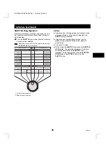
Page 39: ...d to enter the password in order to operate the VCR Setting the 4 digit security lock 1 Press the SECURITY LOCK button ø appears on the digital display 2 Use the JOG dial and SHUTTLE ring to set the 4 digit pass word JOG dial To select a digit SHUTTLE ring To move between digits ø When the 4th digit is entered and the SHUTTLE ring is then turned clockwise the lock is engaged and ö appears on the d...

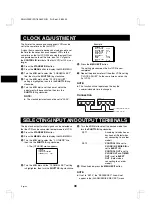
Page 40: ...ll the other VCRs setting CLOCK ADJUST to the same time as set on the first VCR NOTE œ This function will not operate on the day the summer standard time is changed Connection SELECTING INPUT AND OUTPUT TERMINALS The input and output terminal signals can be selected so that the VCR can be connected to older models of VCR 1 Press the STANDBY ON button 2 Press the MENU button to display the MAIN MEN...

Page 41: ...the SHUTTLE ring clockwise 7 Turn the JOG dial to select the desired operation then turn the SHUTTLE ring clockwise SLAVE The function is restricted to only the VCR being operated MASTER The function is applied to the VCR being operated and all VCRs that are connected after it 8 Press the MENU EXIT button NOTE œ The EJECT button will not be operative during recording mode Connection Eject input SE...

Page 42: ...g statuses and menus after carrying out each operation Connection Operator Mode This mode lets you carry out basic operations ejecting recording stopping rewinding changing the recording speed mode and power on stand by NOTE œ This mode will not work correctly unless the VCRs are in the same initial state 1 Press the STANDBY ON button 2 Press the MENU button to display the MAIN MENU 3 Turn the JOG...

Page 43: ... œ This mode will not work correctly unless the VCRs are in the same initial state œ Menu settings will not work correctly unless the menu settings for the VCRs are the same Set the menu settings for each VCR to the initial setting before using this mode to change the settings œ If a power failure occurs make the settings again 1 Press the STANDBY ON button 2 While holding the STOP button press th...

Page 44: ...isplay the MAIN MENU 3 Turn the JOG dial to select the 9 OTHERS line then turn the SHUTTLE ring clockwise ø The OTHERS menu appears OTHERS ALARM LOG POWER FAILURE DEW TERMINAL SET SET1 RS 485 SET STATUS INFO Y ALARM INFO Y 4 Turn the JOG dial until the STATUS INFO setting is highlighted then turn the SHUTTLE ring clockwise 5 Turn the JOG dial to set the STATUS INFO setting then turn the SHUTTLE ri...

Page 45: ...RECOVERY 25 12 07 30 DEW 001 FAILURE 25 12 11 00 RECOVERY 25 12 12 00 USED TIME VIDEO 00003H POWER 00007H POWER FAILURE The number of power failures and the date and time of the most recent power failure and recovery are displayed DEW The number of failures due to condensation and the date and time of the most recent failure and recovery are displayed USED TIME The video heads usage duration and t...

Page 46: ...red mode then turn the SHUTTLE ring clockwise 8 00 6 00 The output becomes 0 V Low when the tape counter reaches 8H 00M 00S or 6H 00M 00S and or when the tape reaches the end END The output becomes 0 V Low when the tape reaches the end NOTES œ If the TAPE in the GENERAL SET menu is set to E 180 6 00 will be indicated instead of 8 00 œ If the SERIES REC is set to Y in the ALARM SERIES REC SET menu ...

Page 47: ...ed output timing then turn the SHUTTLE ring clockwise FIELD 1 pulse is output after each set number of fields FRAME 1 pulse is output after each set number of frames 6 Turn the SHUTTLE ring clockwise 7 Turn the JOG dial to select the desired pulse signal interval 1 2 3 4 5 10 30 or 60 then turn the SHUTTLE ring clockwise œ If TIMING is set to FRAME see step 5 FRAME will be indicated instead of FIE...

Page 48: ...CR enters a mode other than recording i e recording pause stop mode etc during recording MECHA PROBLEM The output becomes 0 V and M appears on the digital display when the tape stops or other problem with the internal mechanism VIDEO LOSS The output becomes 0 V and V appears on the digital display when there is no video signal CLOG DETECT The output becomes 0 V and C appears on the digital display...

Page 49: ...he 3 GENERAL SET line then turn the SHUTTLE ring clockwise ø The GENERAL SET menu appears GENERAL SET TAPE IN MODE STOP TAPE END MODE REW CLOCK ADJUST 01 00 THREAD CHECK N VIDEO LOSS N CLOG DETECT N REMOTE MENU VIDEO COLOR VERTICAL SYNC Y TAPE E 240 4 Turn the JOG dial until the REMOTE setting is highlighted then turn the SHUTTLE ring clockwise 5 Turn the JOG dial to select the desired switch mode...

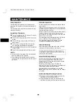
Page 50: ... unlikely thanks to the automatic head cleaning function but due to factors such as the use of poor quality tape and the usage environment the heads could become dirty in a short time The video heads should be inspected every 1 000 hours of use to determine if they need to be replaced The video heads usage can be checked using the POWER FAILURE DEW USED TIME menu Cabinet Cleaning Clean the outside...

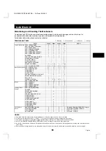
Page 51: ... E ASSY BRAKE T E E E E ASSY BRAKE CAPSTAN E E E E ASSY BRAKE SOFT T E k Loading Drive System ASSY LOADING MOTOR E k DAMPER k COMPL GEAR WORM E k CAM MAIN k SPECIAL WASHER 3 6 X 0 5 E k GEAR WHEEL 1 k GEAR WHEEL 2 E k GEAR RELAY PINCH OPT k SLIDE CRECENT E k GEAR LOAD S E k GEAR RACK FRONT E k GEAR RACK START E k GEAR PINON E k Performance Check BACK TENSION TORQUE E E E E PB BACK TENSION TORQUE 2...

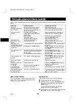
Page 52: ...ly The unit is not set to timer recording stand by mode Press the TIMER button to display n on the digital display N is selected for the timer recordings Be sure to select Y for the programmed timer recordings Alarm recording is not possible OFF appears on the digital display Press the EJECT STOP or PLAY button or turn the SHUTTLE ring to turn the indicator off Noise in the playback picture The vi...

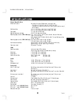
Page 53: ...ignal FM recording Chrominance signal Down converted direct recording Video input 1 V p p BNC 75 Ω unbalanced Video output 1 V p p BNC 75 Ω unbalanced Horizontal resolution Black white mode 350 line or more Colour mode 250 line or more Audio Input 8 dBs RCA pin jack 27 kΩ unbalanced Output 8 dBs RCA pin jack 600 Ω unbalanced Microphone input 60 dBs 3 5 mm mini jack 10 kΩ unbalanced Connectors Alar...

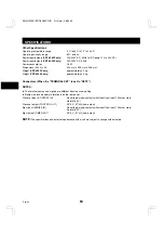
Page 54: ...ors When the TERMINAL SET is set to SET2 NOTES œ The terminal names and signals are different from the usual setting œ Names in brackets apply to terminals on the rear panel Clock set input CONTROL IN No voltage make contact switch input Low input 100ms or more Normally 5 V Clock set output CONTROL OUT DC 5 V 5 7kΩ Low output Eject input SERIES IN No voltage make contact switch input Low input 100...

Reviews: