– 12 –
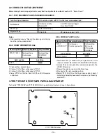
2-2. VIDEO CIRCUIT ADJUSTMENT
Before making the following adjustments, complete the adjustments described in section 2-1. “Servo Circuit.”
2-2-1. TEST EQUIPMENT AND STANDARDS REQUIRED
PAL color bar signal with 100% white level, monoscope signal
Vertical sensitivity
: 5 mV/DIV, external trigger
Bandwidth
: more than 10 MHz
VHS cassette tape
Color Bar Signal Generator
Oscilloscope
Blank Tape
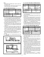
Notes :
• Self-recording means “Record the video signal and play
back the just-recorded portion.”
Alignment tape
PLAYBACK
mode
Measuring Point
VR141
Adj. Location
TP141, TP142
2-2-2. SKEW CORRECTION ADJ.
Measuring Equipment
Adj. Condition
Alignment tape
Oscilloscope
Adj. Value
1. Playback the alignment tape.
2. Connect CH1 of the oscilloscope to TP141.
3. Connect CH2 of the oscilloscope to TP142.
4. Adjust VR141 so that the Y level of CH1 and CH2 becomes
a minimum.
Measuring Point
Adj. Location
VR131 (2H-DL)
TP101
or VIDEO OUT
2-2-3. 2H DELAY LEVEL ADJ.
Measuring Equipment
Adj. Condition
Self-recording
(8H) mode
STILL mode
Blank tape
Adj. Value
Oscilloscope
Color bar generator
1. Terminate TP101 (or VIDEO OUT) and ground with a 75
Ω
resistor or connect the monitor TV to the VIDEO OUT terminal.
2. Connect the color bar generator (monoscope signal) to the
VIDEO IN terminal.
3. Record the color bar signal on the blank tape.
4. Play back of the just-recorded portion.
5. Adjust VR131 (2H-DL) so that the luminance signal level of
switching alternately becomes the same or no flicker by
monitor TV.
Alignment tape
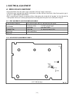
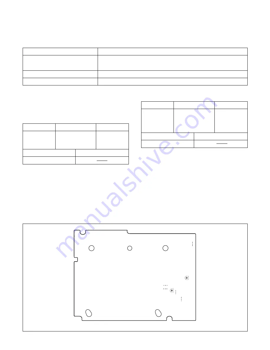
3. TEST POINTS FOR TAPE PATH ADJUSTMENT
VR141
VR131
TP101
TP141
TP183
TP142
TP182
CP-1 PWB (Foil side)
Test points TP182 (ENV) and TP183 (SW-P) for tape path adjustment are shown in figure below.
VHJ-0008
: SP mode, color bar, 1 kHz


