-34-
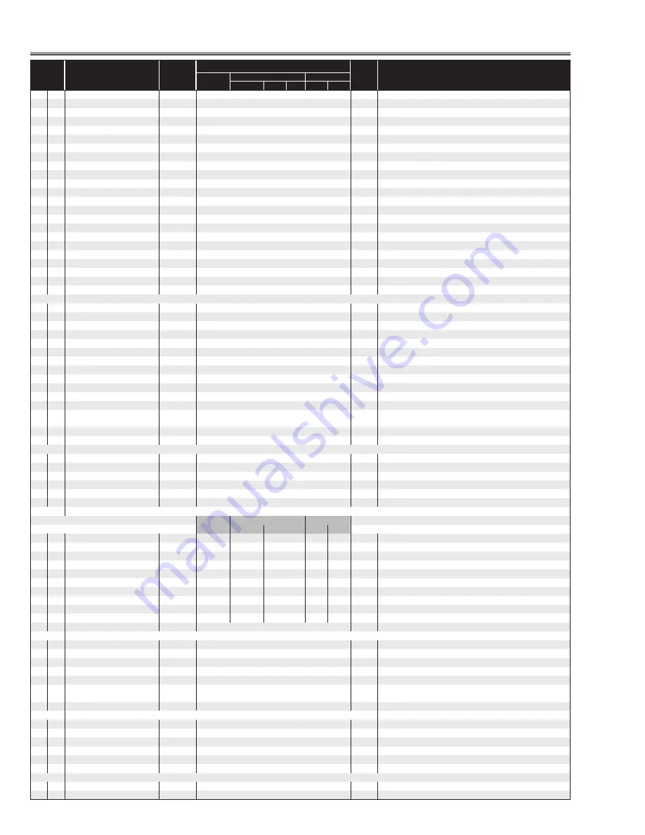
Electrical Adjustments
Item No.
NAME
Device
XGA
Range Description
PC
Component
Video
HDTV
480p
480i NTSC
PAL
2
B-LCCOM
L3E06150
300
0-511
✻
Common Center Adj.
3
R-LCCOM-Gain
L3E06150
191
0-255
4
G-LCCOM-Gain
L3E06150
191
0-255
5
B-LCCOM-Gain
L3E06150
191
0-255
6
R-LCCOM-Bright
L3E06150
0
0-255
7
G-LCCOM-Bright
L3E06150
0
0-255
8
B-LCCOM-Bright
L3E06150
0
0-255
9
R-LCCOM-Cent
L3E06150
18
0-63
10
G-LCCOM-Cent
L3E06150
18
0-63
11
B-LCCOM-Cent
L3E06150
18
0-63
12
R-ENBX-PW
L3E01060
11
0-127
13
G-ENBX-PW
L3E01060
11
0-127
14
B-ENBX-PW
L3E01060
11
0-127
15
R-DXIN
L3E01060
9
0-255
Link with Group 10 - No 18
16
G-DXIN
L3E01060
9
0-255
Link with Group 10 - No 19
17
B-DXIN
L3E01060
9
0-255
Link with Group 10 - No 20
18
R-CLXIN
L3E01060
9
0-255
Link with Group 10 - No 15
19
G-CLXIN
L3E01060
9
0-255
Link with Group 10 - No 16
20
B-CLXIN
L3E01060
9
0-255
Link with Group 10 - No 17
21
R-ENBX1IN
L3E01060
27
0-255
22
G-ENBX1IN
L3E01060
27
0-255
23
B-ENBX1IN
L3E01060
27
0-255
Group 100 OPTION (Lamp Time, Service Port etc)
1
RS232C Baudrate
PW186
0
0 : 19200bps 1: 9600bps
2
PJLink Enable
MCI
1
0-1
0:Disable 1:Enable
5
PW Debug Command Enable
PW186
1
0-1
0:Disable 1:Enable(Sanyo Serial Command Disable)(Not memorized)
6
Device Refresh Disable
PW186
0
0-1
0:Enable 1:Disable(Not memorized)
20
Projector Time Reset
PW186
0
0-20
Resets Projector time when the value is set to 10.
21
Lamp Warning Time (HIGH)
PW186
1500
0-10000 Normal lamp warning time
22
Lamp Warning Time (NORMAL)
PW186
3000
0-10000 Eco lamp warning time
30
Lamp life test enable
PW186
0
0-1
0:Disable 1:Enable For safety test purpose
31
Lamp On time for life test
PW186
1
1-720
For test purpose
32
Lamp Off time for life test
PW186
3
1-720
For test purpose
33
Lamp total time for life test
PW186
0
0-32767 For test purpose
34
Input Search Wait Time
PW186
2300
1000-3000
Waiting time of Input Search Switch (ms)
40
Memory viewer please wait display
disable
PW186
0
0-1
0: disable 1:Enable, Prohibit a part of Memory Viewer function
50
RC Mode
PW186
0
0-1
RC Code: 0: Promethean
Group 101 OPTION (Signal Processing)
2
3
Frame Lock SW
PW186
0
0:Not V-Sync, 1:V-Sync
5
Non Brand
PW186
0
0:Normal1:Non Brand
6
Monitor Error Count
PW186
5
Threshold value of Monitor error count
7
CABLE SW
PW186
0
Cable switch
Group 103 PW186 Image Control
PC
COMPONENT
VIDEO
PC
HDTV
480i
VIDEO SCART
0
Center Contrast
PW186
600
512
650
512
512
PW186 CONTRAST Center adjustment
✻
Gain Adj. (Video)
1
Center Brightness
PW186
512
512
512
512
512
PW186 BRIGHTNESS Center adjustment
2
Center Color
PW186
512
475
475
475
425
PW186 COLOR Center adjustment
3
Center Tint
PW186
90
82
82
82
82
PW186 TINT Center adjustment
4
Center Sharpness
PW186
16
16
16
16
16
PW186 SHARPNESS Center adjustment
5
Alpha Contrast
PW186
40
40
40
40
40
PW186 CONTRAST Range adjustment
6
Alpha Brightness
PW186
140
140
140
140
140
PW186 BRIGHTNESS Range adjustment
7
Alpha Color
PW186
70
70
70
70
70
PW186 COLOR Range adjustment
8
Alpha Tint
PW186
10
10
10
10
10
PW186 TINT Range adjustment
9
Alpha Sharpness
PW186
10
10
10
10
10
PW186 SHARPNESS Range adjustment
Group 104 PW186 Auto PC Adjust Control
0
AutoPCAdjustEnable
PW186
0
0-1
0:Auto1:Prohibit Auto PC Adj.
1
Frequency Step
PW186
2
0-3
2
Frequency Threshold
PW186
5
0-10
3
Fine Phase
PW186
1
0-1
4
BLKDET
PW186
1
0-3
Black Level Detecte Area
5
PHASEMSK
PW186
0
0-3
Phase Detection Filter0:Effect all bits1:Disable lower 1 bit2:Disable lower 2
bits 3:Disable lower 3 bits
Group 105 Custom Mode
0
H/V
PW186
0
0-1
Link H and V, 1: On, 0: Off
1
Scale-H
PW186
100/100/100/100
0-200
Vertical Scaler Edit (Unit %) (PC, Component)/(Scart)/(Composite, S-video)
2
Scale-V
PW186
100/100/100/100
0-200
Vertical Position Correction (Unit %)
3
RESET/STORE
PW186
100/100/100/100
0-200
Reset Vertical Aspect 0:Reset, 1:Save0
4
Horizontal Scaler
PW186
100/100/100/100
0-200
Horizontal Scaler Edit (Unit %)
5
CUSTOM ON/OFF
PW186
0
0-1
*Not used
Group 110 Dimmer Processing for Ballast type
0
DIMMER_CTRL_LEVEL1
PW186
11
0-255
1
DIMMER_CTRL_LEVEL2
PW186
21
0-255
Summary of Contents for Think GAIA PLC-XE45
Page 28: ... 28 Electrical Adjustments 40 2 0 3 40 40 2 40 40 MAIN BOARD Test Points and Locations ...
Page 53: ... 53 BA7078 Sync Separator IC5301 IC Block Diagrams BA9743 DDC Control IC5651 ...
Page 54: ... 54 IC Block Diagrams L3E6100D D A S H LCD Driver IC501 IC531 IC561 FA5502 P F Control IC621 ...
Page 56: ... 56 IC Block Diagrams M62334 D A IC3571 NJW1141 Audio Control IC5001 ...
Page 57: ... 57 IC Block Diagrams STR Z2156A Power Switching IC631 uPD64012 Video Decoder IC101 ...
Page 87: ...KJ7 XE4500 87 Mechanical Parts List ...
Page 88: ... KJ7AC Feb 2008 DC 300 Printed in Japan SANYO Electric Co Ltd ...


